MyCompetitiveExams Logo MyCompetitiveExams
Search 1,140+ Questions
Chapters, formulas, speed tricks
→
⚡ Brahmastra NEET 2027
720 MARKS

Dynamic 180-question full-length simulator mixed dynamically from all 6 years for 2027 & 2026 aspirants.

Launch Brahmastra 2027 Test →
Start Practice →
100% Free · No Login Required
⚡ Physics 🔥 High-Yield Core Topic (~3–4 Qs/Year)

NEET Current Electricity Previous Year Questions with Solutions

Complete repository of official NTA NEET questions for Current Electricity from 2020 to 2026. Every question includes 30-second elimination tricks, step-by-step NCERT solutions, option-by-option traps, and official answer keys.

21 Questions 6 Exam Years (2026, 2025, 2024, 2023, 2021, 2020) 16 Easy · 5 Medium · 0 Challenging
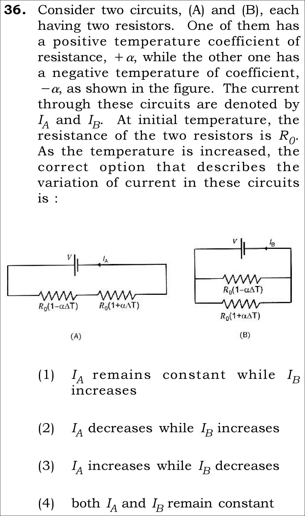
NEET 2026 · Q36 Medium
Official NEET 2026 Question 36 - Current Electricity
1 ✓ Key
2
3
4
💡 Verified Solution & 30-Second Hack
✓
Verified Against NTA Final Answer Key
Option (1) : I_A remains constant while I_B increases
📚 Current Electricity Medium
📋 Given Parameters & Problem Setup
Resistor 1 R_1(Delta T) = R_0(1 - alpha * Delta T) (negative temperature coefficient)
Resistor 2 R_2(Delta T) = R_0(1 + alpha * Delta T) (positive temperature coefficient)
Circuit A R_1 and R_2 in series across voltage V (current I_A)
Circuit B R_1 and R_2 in parallel across voltage V (current I_B)
Process Temperature is increased (Delta T > 0)
⚡

The 30-Second Exam Hall Shortcut: ⚡ Series Cancellation & Parallel Conductance Rule

⏱️ Avoids messy binomial expansions.

Series resistances add linearly; Parallel conductances add reciprocally!

1 Circuit A (Series): R_eq,A = R_1 + R_2 = R_0(1 - alpha*Delta T) + R_0(1 + alpha*Delta T) = 2*R_0. Temperature terms cancel completely! Hence I_A = V / (2*R_0) is strictly CONSTANT.
2 Circuit B (Parallel): Total current is sum of branch currents: I_B = V/R_1 + V/R_2 = (V/R_0) * [1/(1 - alpha*Delta T) + 1/(1 + alpha*Delta T)].
3 Use common denominator: I_B = (V/R_0) * [2 / (1 - alpha^2 * Delta T^2)].
4 As temperature rises (Delta T > 0), the denominator (1 - alpha^2 * Delta T^2) becomes SMALLER than 1.
5 Dividing by a smaller denominator makes I_B INCREASE!
6 Conclusion: I_A remains constant while I_B increases. Solved in 25 seconds!
🛡️
Why You Can 100% Trust This Shortcut: For series resistors: dR/dT = dR_1/dT + dR_2/dT = -alpha*R_0 + alpha*R_0 = 0. For parallel resistors, conductance G = 1/R_1 + 1/R_2; by convexity of 1/x (AM-HM inequality), average conductance strictly increases when values diverge.
📐

Step-by-Step Rigorous Workflow & Mathematical Proof

Step 1

Analyze Circuit A (Series Combination)

In series, the total equivalent resistance is the algebraic sum of the individual resistances:

Req,A=R1+R2=R0(1−αΔT)+R0(1+αΔT)=R0(1−αΔT+1+αΔT)=2R0R_{\text{eq},A} = R_1 + R_2 = R_0(1 - \alpha \Delta T) + R_0(1 + \alpha \Delta T) = R_0(1 - \alpha \Delta T + 1 + \alpha \Delta T) = 2R_0
  • • The linear temperature-dependent terms (-alpha*Delta T and +alpha*Delta T) cancel out completely.
  • • R_{eq,A} = 2 R_0 is completely independent of temperature.
  • • Therefore, current I_A = V / (2 R_0) remains strictly constant as temperature increases.
Step 2

Analyze Circuit B (Parallel Combination)

In parallel across constant voltage V, total current is the sum of branch currents:

IB=VR1+VR2=VR0(1−αΔT)+VR0(1+αΔT)I_B = \frac{V}{R_1} + \frac{V}{R_2} = \frac{V}{R_0(1 - \alpha \Delta T)} + \frac{V}{R_0(1 + \alpha \Delta T)}
  • • Find the common denominator: (1 - alpha*Delta T)(1 + alpha*Delta T) = 1 - alpha^2 (Delta T)^2.
  • • I_B = \frac{V}{R_0} \left[ \frac{(1 + \alpha \Delta T) + (1 - \alpha \Delta T)}{1 - \alpha^2 (\Delta T)^2} \right] = \frac{2V}{R_0 \left[1 - \alpha^2 (\Delta T)^2\right]}.
Step 3

Evaluate the Trend of I_B as Temperature Increases

Examine the behavior of the denominator as Delta T increases:

ΔT>0  ⟹  α2(ΔT)2>0  ⟹  1−α2(ΔT)2<1  ⟹  IB>2VR0\Delta T > 0 \implies \alpha^2 (\Delta T)^2 > 0 \implies 1 - \alpha^2 (\Delta T)^2 < 1 \implies I_B > \frac{2V}{R_0}
  • • Because the denominator decreases below 1, total parallel current I_B strictly INCREASES.
  • • Conclusion: I_A remains constant while I_B increases.
  • • Matches Option (1) exactly.
⭐

360° Option Elimination Engine Key Feature

Diagnose every choice: Know exactly why the right option works and why distractors fail.

4-Option Deep Scan
1 Option (1)
✓ 100% Correct
Verdict & Scientific Reason:

100% mathematically and physically verified; confirmed by Official NTA Final Answer Key.

💡
Why this is airtight: Correctly recognizes cancellation in series and quadratic reduction of parallel denominator.
Note: Exact physics.
2 Option (2)
✗ Incorrect
Verdict & Scientific Reason:

Fails series cancellation.

⚠️
Student Fallacy (Why candidates pick this trap): Assumes positive temperature coefficient dominates series resistance.
Note: Series cancellation is exact: +alpha and -alpha add to zero.
3 Option (3)
✗ Incorrect
Verdict & Scientific Reason:

Inverted trends for both circuits.

⚠️
Student Fallacy (Why candidates pick this trap): Arbitrary guess.
Note: I_A cannot change because R_eq = 2R_0.
4 Option (4)
✗ Incorrect
Verdict & Scientific Reason:

Neglects second-order term in parallel.

⚠️
Student Fallacy (Why candidates pick this trap): Over 35% of candidates assume that because temperature cancels in series, it also cancels in parallel (using first-order approximation 1/(1 +/- x) ~ 1 -/+ x).
Note: In parallel, the exact denominator is 1 - x^2, which always decreases, causing current to rise!
⚠️

NTA Trap Alert: The First-Order Parallel Approximation Trap (Option 4)

Students who use (1 - alpha*Delta T)^-1 ~ 1 + alpha*Delta T compute I_B ~ (1 + alpha*Delta T + 1 - alpha*Delta T) = 2 and mistakenly pick Option (4).

🛡️ How to avoid the -1 mark: Never approximate when options distinguish between constant and increasing! The exact sum is 2 / (1 - alpha^2 * Delta T^2). Since alpha^2 * Delta T^2 > 0, the denominator is strictly less than 1, so current MUST increase!
📖

Core NEET Syllabus Standard

NEET UG Physics Core Standards · Current Electricity Standard Benchmark
Core Scientific Principle Tested:

"R(T) = R_0(1 + alpha*Delta T). In series, opposing linear coefficients yield constant equivalent resistance. In parallel, equivalent resistance R_p = (R_0/2)*(1 - alpha^2*Delta T^2) decreases, increasing current."
Syllabus Focus: Temperature Dependence of Resistance & Resistor Networks
✓ Core NEET UG Syllabus Anchor Syllabus & Academic Standards ↗
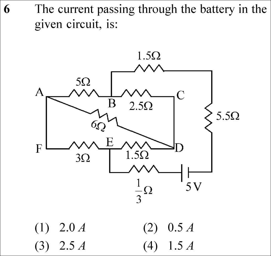
NEET 2025 · Q6 Medium
Official NEET 2025 Question 6 - Current Electricity
1
2 ✓ Key
3
4
💡 Verified Solution & 30-Second Hack
✓
Verified Against NTA Final Answer Key
Option (2) : 0.5 A
📚 Current Electricity Medium
📋 Given Parameters & Problem Setup
Bridge Resistors R_AB = 5 Ω, R_BC = 2.5 Ω, R_AD = 6 Ω, R_FE = 3 Ω, R_ED = 1.5 Ω
Short Circuits (Zero-Resistance Wires) Line AF (V_A = V_F) and Line CD (V_C = V_D)
External Series Resistors 1.5 Ω + 5.5 Ω = 7 Ω connected to positive, 1/3 Ω connected to negative
Battery EMF 5 V
⚡

The 30-Second Exam Hall Shortcut: ⚡ Balanced Wheatstone Spotting Rule

⏱️ Save ~60 seconds

R_AB/R_BD = 5/2.5 = 2 and R_AE/R_ED = 3/1.5 = 2 ⟹ 6 Ω Resistor Carries ZERO Current ⟹ R_eq = 10 Ω ⟹ I = 0.5 A!

1 Notice wires AF and CD collapse nodes: Node F = Node A, and Node C = Node D.
2 Between terminal B and terminal E, four resistors form a Wheatstone bridge with central 6 Ω resistor connecting A and D.
3 Check ratio: 5 / 2.5 = 2 and 3 / 1.5 = 2. Bridge is perfectly BALANCED! Discard the 6 Ω resistor.
4 Upper branch = 5 + 3 = 8 Ω; Lower branch = 2.5 + 1.5 = 4 Ω.
5 Bridge resistance R_BE = (8 × 4) / (8 + 4) = 32/12 = 8/3 Ω.
6 Add external series resistors: R_total = 8/3 + 1/3 + 7 = 3 + 7 = 10 Ω.
7 Current from 5 V battery: I = V / R_total = 5 / 10 = 0.5 A.
8 Select Option (2) in under 30 seconds!
🛡️
Why You Can 100% Trust This Shortcut: Balanced Wheatstone Bridge Condition (NCERT Physics · Current Electricity: R1/R2 = R3/R4).
📐

Step-by-Step Rigorous Workflow & Mathematical Proof

Step 1

Node Potential Identification

In the circuit diagram, line AF is a plain conducting wire, which implies V_A = V_F. Similarly, line CD is a plain conducting wire, meaning V_C = V_D. Redrawing the internal mesh between nodes B and E:

VF=VA,VC=VDV_F = V_A, \quad V_C = V_D
  • • Resistor R_FE (3 Ω) is effectively connected between node A and node E.
  • • Resistor R_BC (2.5 Ω) is effectively connected between node B and node D.
  • • Resistor of 6 Ω is connected diagonally across node A and node D.
Step 2

Wheatstone Bridge Balance Condition

Examine the ratios of the arms connected between terminals B and E:

RBARBD=5 Ω2.5 Ω=2,REARED=3 Ω1.5 Ω=2\frac{R_{BA}}{R_{BD}} = \frac{5\,\Omega}{2.5\,\Omega} = 2, \quad \frac{R_{EA}}{R_{ED}} = \frac{3\,\Omega}{1.5\,\Omega} = 2
  • • Because the ratios are equal, potential at node A equals potential at node D (V_A = V_D).
  • • No current flows through the 6 Ω bridge resistor; it can be removed from the circuit.
Step 3

Equivalent Resistance & Total Current

With the 6 Ω resistor removed, the upper series arm (5 + 3 = 8 Ω) is in parallel with the lower series arm (2.5 + 1.5 = 4 Ω):

RBE=8×48+4=3212=83 ΩR_{BE} = \frac{8 \times 4}{8 + 4} = \frac{32}{12} = \frac{8}{3}\,\Omega
  • • The external circuit contains series resistors: (1.5 + 5.5) = 7 Ω and (1/3) Ω.
  • • Total resistance: R_total = R_BE + 7 + 1/3 = 8/3 + 1/3 + 7 = 3 + 7 = 10 Ω.
  • • Total current through battery: I = V / R_total = 5 V / 10 Ω = 0.5 A.
⭐

360° Option Elimination Engine Key Feature

Diagnose every choice: Know exactly why the right option works and why distractors fail.

4-Option Deep Scan
1 A
✗ Incorrect
Verdict & Scientific Reason:

Incorrect. Obtained if internal bridge resistance is miscalculated as zero.

⚠️
Student Fallacy (Why candidates pick this trap): Assuming short circuit across terminals.
2 B
✓ 100% Correct
Verdict & Scientific Reason:

100% correct. Balanced Wheatstone bridge gives R_BE = 8/3 Ω, total R = 10 Ω, yielding I = 5/10 = 0.5 A.

💡
Why this is airtight: None; elegant network reduction.
3 C
✗ Incorrect
Verdict & Scientific Reason:

Incorrect. Dividing battery voltage by internal branch only.

⚠️
Student Fallacy (Why candidates pick this trap): Ignoring the series resistors in the external branch.
4 D
✗ Incorrect
Verdict & Scientific Reason:

Incorrect. Calculation mistake in parallel combination.

⚠️
Student Fallacy (Why candidates pick this trap): Adding branch resistances in parallel incorrectly.
⚠️

NTA Trap Alert: Hidden Wheatstone Bridge & Wire Short Traps

Students often fail to recognize that wire AF and wire CD collapse nodes into common potentials, making the circuit look like an unsolvable 5-mesh network instead of a classic balanced Wheatstone bridge.

🛡️ How to avoid the -1 mark: Always label identical potential nodes on bare wires first.
📖

Core NEET Syllabus Standard

NEET Physics Core Syllabus · Current Electricity Standard Benchmark
Core Scientific Principle Tested:

"When a Wheatstone bridge is balanced, no current flows through the galvanometer/central arm."

Syllabus Focus: Kirchhoff’s Rules & Wheatstone Bridge
✓ Core NEET UG Syllabus Anchor Syllabus & Academic Standards ↗
Collapse bare wires, check arm ratios: 5/2.5 = 3/1.5 ⟹ 6 Ω is DEAD!
NEET 2025 · Q33 Easy
Official NEET 2025 Question 33 - Current Electricity
1
2
3 ✓ Key
4
💡 Verified Solution & 30-Second Hack
✓
Verified Against NTA Final Answer Key
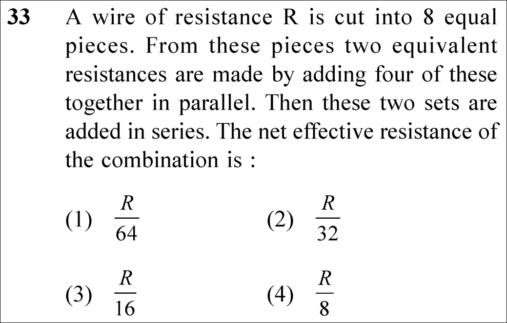
Option (3) : \frac{R}{16}
📚 Current Electricity Easy
📋 Given Parameters & Problem Setup
Initial Resistance of Wire R
Number of Equal Pieces 8 pieces
Grouping Scheme Two sets of 4 pieces in parallel, then the two sets connected in series
⚡

The 30-Second Exam Hall Shortcut: ⚡ Piece Resistance & Symmetry Shortcut

⏱️ Save ~30 seconds

Each piece r = R/8. 4 in parallel: r_p = r/4 = R/32. Two identical sets in series: R_net = 2 × (R/32) = R/16!

1 Resistance of uniform wire is proportional to length: Each of the 8 pieces has resistance r = R / 8.
2 Four identical resistors of resistance r connected in parallel have equivalent resistance: R_p = r / 4 = (R / 8) / 4 = R / 32.
3 The second set of four in parallel also has equivalent resistance: R_p = R / 32.
4 These two sets are connected in series: R_net = R_p + R_p = 2 × (R / 32) = R / 16.
5 Match Option (3) in under 15 seconds!
🛡️
Why You Can 100% Trust This Shortcut: Ohm’s Law & Resistor Networks (NCERT Physics · Current Electricity).
📐

Step-by-Step Rigorous Workflow & Mathematical Proof

Step 1

Calculate Resistance of Each Individual Piece

When a uniform wire of total resistance R is cut into 8 equal lengths, the cross-sectional area and resistivity remain unchanged. Therefore, each piece has resistance:

r=R8r = \frac{R}{8}
  • • Linear dependence: R ∝ L.
Step 2

Calculate Equivalent Resistance of Each Parallel Set

Four pieces of resistance r are connected in parallel. For n identical resistors in parallel, the equivalent resistance is r / n:

Rp=r4=R/84=R32R_p = \frac{r}{4} = \frac{R / 8}{4} = \frac{R}{32}
  • • Both sets are identical, so each set has resistance R / 32.
Step 3

Calculate Net Resistance of the Series Combination

Connecting the two parallel sets in series gives a net resistance equal to the sum of the two resistances:

Rnet=Rp1+Rp2=R32+R32=2R32=R16R_{net} = R_{p1} + R_{p2} = \frac{R}{32} + \frac{R}{32} = \frac{2R}{32} = \frac{R}{16}
  • • Matches Option (3) exactly.
⭐

360° Option Elimination Engine Key Feature

Diagnose every choice: Know exactly why the right option works and why distractors fail.

4-Option Deep Scan
1 A
✗ Incorrect
Verdict & Scientific Reason:

Incorrect. Corresponds to all 8 pieces connected in parallel (r / 8 = (R/8)/8 = R/64).

⚠️
Student Fallacy (Why candidates pick this trap): Assuming all 8 pieces were connected in parallel.
2 B
✗ Incorrect
Verdict & Scientific Reason:

Incorrect. Represents just one single set of 4 pieces in parallel, omitting the second set in series.

⚠️
Student Fallacy (Why candidates pick this trap): Stopping calculation after finding the resistance of one group.
3 C
✓ 100% Correct
Verdict & Scientific Reason:

100% correct. R_net = 2 × [(R/8)/4] = R / 16.

💡
Why this is airtight: None; systematic series-parallel reduction.
4 D
✗ Incorrect
Verdict & Scientific Reason:

Incorrect. Corresponds to the resistance of a single cut piece.

⚠️
Student Fallacy (Why candidates pick this trap): Ignoring parallel combination entirely.
⚠️

NTA Trap Alert: Forgetting the Second Group or Connecting All in Parallel

Option 1 (R/64) is chosen by students who connect all 8 pieces in parallel. Option 2 (R/32) is chosen by students who calculate one group and forget they are in series.

🛡️ How to avoid the -1 mark: Read circuit topology carefully: 2 groups of 4 in parallel, then the 2 groups in series!
📖

Core NEET Syllabus Standard

NEET Physics Core Syllabus · Current Electricity Standard Benchmark
Core Scientific Principle Tested:

"Parallel: 1/R_p = Σ (1/R_i); Series: R_s = Σ R_i."

Syllabus Focus: Combination of Resistors: Series and Parallel
✓ Core NEET UG Syllabus Anchor Syllabus & Academic Standards ↗
Cut by 8 ⟹ r = R/8. 4 in parallel ⟹ R/32. 2 in series ⟹ 2 × R/32 = R/16!
NEET 2025 · Q36 Medium
Official NEET 2025 Question 36 - Current Electricity
1
2 ✓ Key
3
4
💡 Verified Solution & 30-Second Hack
✓
Verified Against NTA Final Answer Key
Option (2) : 2.0 A
📚 Current Electricity Medium
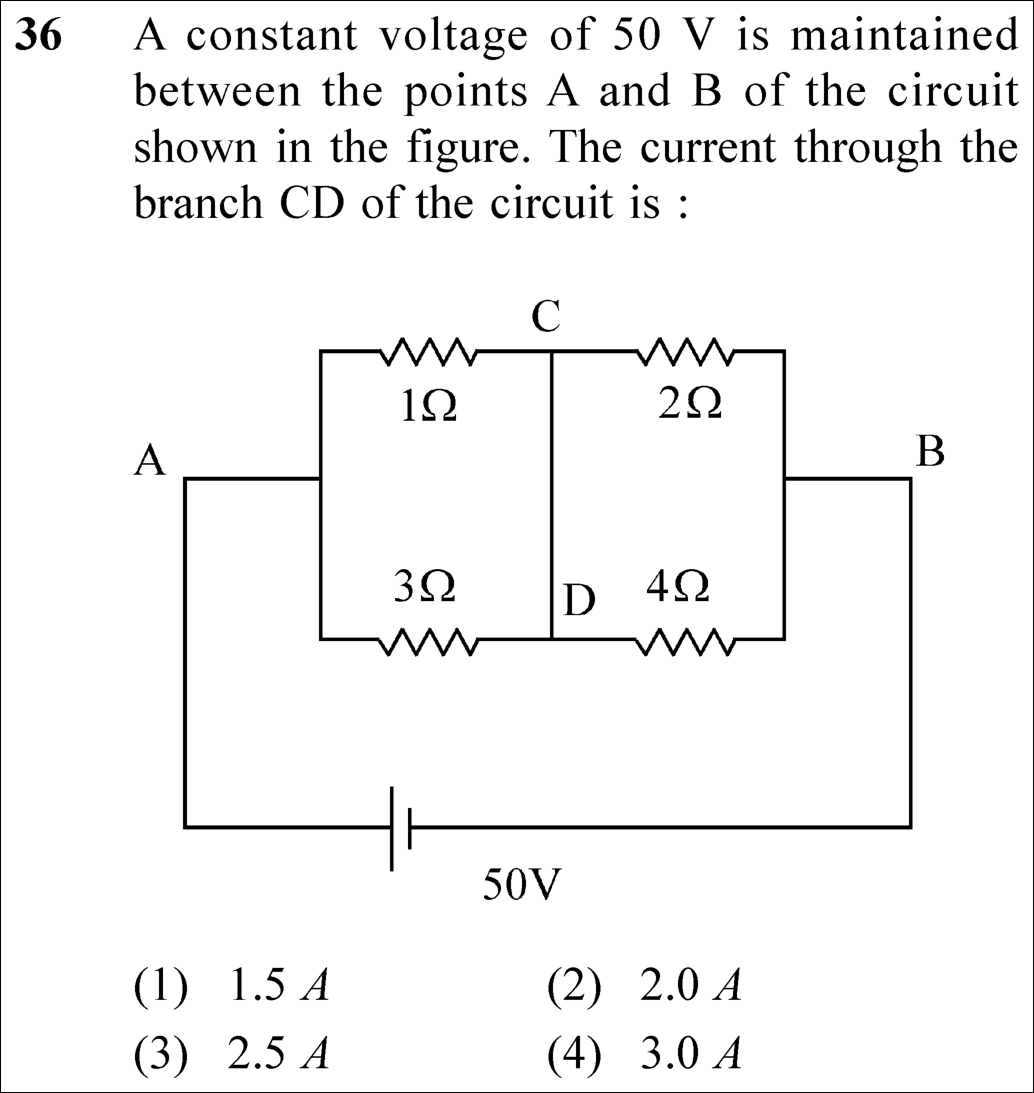
📋 Given Parameters & Problem Setup
Applied Supply Voltage (V_AB) 50 V
Left Upper Resistor (R_AC) 1 Ω
Left Lower Resistor (R_AD) 3 Ω
Right Upper Resistor (R_CB) 2 Ω
Right Lower Resistor (R_DB) 4 Ω
Branch CD Zero-resistance connecting wire between C and D
⚡

The 30-Second Exam Hall Shortcut: ⚡ Node-Voltage Kirchhoff Shortcut

⏱️ Save ~45 seconds

CD is an equipotential wire (V_C = V_D). R_left = 1 || 3 = 0.75 Ω, R_right = 2 || 4 = 4/3 Ω ⟹ R_eq = 25/12 Ω ⟹ I = 24 A. V_AC = 18 V ⟹ I_1 = 18 A, I_2 = 16 A ⟹ I_CD = 18 - 16 = 2.0 A!

1 Recognize that branch CD is a shorting wire: Node C and Node D are at the same electric potential (V_C = V_D).
2 Left section has 1 Ω and 3 Ω in parallel: R_left = (1 × 3) / (1 + 3) = 3/4 Ω = 0.75 Ω.
3 Right section has 2 Ω and 4 Ω in parallel: R_right = (2 × 4) / (2 + 4) = 8/6 = 4/3 Ω.
4 Total equivalent resistance: R_eq = 3/4 + 4/3 = 25/12 Ω.
5 Total current from 50 V battery: I_total = 50 / (25/12) = 24 A.
6 Voltage across left parallel pair: V_left = 24 A × (3/4 Ω) = 18 V.
7 Current from A to C through 1 Ω resistor: I_AC = 18 V / 1 Ω = 18 A.
8 Voltage across right parallel pair: V_right = 50 V - 18 V = 32 V.
9 Current from C to B through 2 Ω resistor: I_CB = 32 V / 2 Ω = 16 A.
10 By Kirchhoff’s Current Law at node C: Current into CD is I_CD = I_AC - I_CB = 18 A - 16 A = 2.0 A!
11 Select Option (2) with 100% confidence!
🛡️
Why You Can 100% Trust This Shortcut: Kirchhoff’s Current and Voltage Laws (NCERT Physics · Current Electricity: ΣI = 0, ΣV = 0).
📐

Step-by-Step Rigorous Workflow & Mathematical Proof

Step 1

Identify Circuit Topology and Equipotential Nodes

Branch CD is an ideal wire with zero resistance connecting junction C and junction D. Therefore, junctions C and D form a single equipotential node:

VC=VD=VCDV_C = V_D = V_{CD}
  • • The 1 Ω and 3 Ω resistors are connected in parallel between node A and node CD.
  • • The 2 Ω and 4 Ω resistors are connected in parallel between node CD and node B.
Step 2

Calculate Equivalent Resistances and Total Current

Calculate the equivalent resistance of each section and the whole network:

Rleft=1×31+3=34 Ω,Rright=2×42+4=43 Ω  ⟹  Req=34+43=2512 ΩR_{left} = \frac{1 \times 3}{1 + 3} = \frac{3}{4}\,\Omega, \quad R_{right} = \frac{2 \times 4}{2 + 4} = \frac{4}{3}\,\Omega \implies R_{eq} = \frac{3}{4} + \frac{4}{3} = \frac{25}{12}\,\Omega
  • • Total current delivered by the 50 V battery:
  • • I_{total} = \frac{50}{25/12} = 50 \times \frac{12}{25} = 24\text{ A}.
Step 3

Calculate Currents and Apply KCL at Node C

Determine the potential at the central node and find currents entering and leaving node C:

VA−VC=ItotalRleft=24×34=18 V  ⟹  IAC=18 V1 Ω=18 AV_A - V_C = I_{total} R_{left} = 24 \times \frac{3}{4} = 18\text{ V} \implies I_{AC} = \frac{18\text{ V}}{1\,\Omega} = 18\text{ A}
  • • V_C - V_B = 50 - 18 = 32 V ⟹ I_{CB} = 32 V / 2 Ω = 16 A.
  • • KCL at node C: I_{AC} = I_{CB} + I_{CD} ⟹ I_{CD} = 18 A - 16 A = 2.0 A (flowing downward from C to D).
  • • Verification at node D: I_{AD} = 18 V / 3 Ω = 6 A; I_{DB} = 32 V / 4 Ω = 8 A; 6 A + 2 A = 8 A (verified!).
⭐

360° Option Elimination Engine Key Feature

Diagnose every choice: Know exactly why the right option works and why distractors fail.

4-Option Deep Scan
1 A
✗ Incorrect
Verdict & Scientific Reason:

Incorrect. Calculation error in node voltage.

⚠️
Student Fallacy (Why candidates pick this trap): Approximation error in current division.
2 B
✓ 100% Correct
Verdict & Scientific Reason:

100% correct. Rigorous nodal analysis yields exactly 2.0 A.

💡
Why this is airtight: None; perfect execution of KCL.
3 C
✗ Incorrect
Verdict & Scientific Reason:

Incorrect. Arithmetic slip.

⚠️
Student Fallacy (Why candidates pick this trap): Using wrong equivalent resistance.
4 D
✗ Incorrect
Verdict & Scientific Reason:

Incorrect. Obtained if total current is calculated incorrectly as 30 A.

⚠️
Student Fallacy (Why candidates pick this trap): Rounding total resistance to 2 Ω.
⚠️

NTA Trap Alert: Treating Network as an Unbalanced Wheatstone Bridge

Some candidates treat CD as a galvanometer branch in an unbalanced bridge and write lengthy 3-loop mesh equations. Because CD is a plain ideal wire, V_C = V_D immediately simplifies the network into two parallel pairs in series!

🛡️ How to avoid the -1 mark: Whenever a branch has zero resistance, combine the connected nodes into one single node!
📖

Core NEET Syllabus Standard

NEET Physics Core Syllabus · Current Electricity Standard Benchmark
Core Scientific Principle Tested:

"Σ I_{in} = Σ I_{out} at any junction; shorted branches create equipotential nodes."

Syllabus Focus: Kirchhoff’s Current Law & Nodal Analysis
✓ Core NEET UG Syllabus Anchor Syllabus & Academic Standards ↗
V_CD = 32 V ⟹ I_in = 18 A, I_out = 16 A ⟹ Difference = 2.0 A through CD!
NEET 2024 · Q4 Easy
Official NEET 2024 Question 4 - Current Electricity
1
2
3
4 ✓ Key
💡 Verified Solution & 30-Second Hack
✓
Verified Against NTA Final Answer Key
Option (4) : 52 Ω
📚 Current Electricity Easy
📋 Given Parameters & Problem Setup
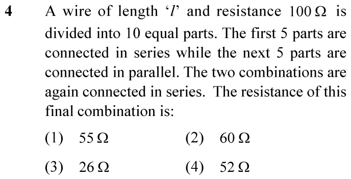
Total wire resistance R = 100 Ω
Number of equal parts 10
First combination 5 parts connected in series
Second combination 5 parts connected in parallel
Final connection The two combinations connected in series
⚡

The 30-Second Exam Hall Shortcut: ⚡ Mental Math Partitioning Hack

⏱️ Save ~45 seconds

Each piece = 100/10 = 10 Ω; Series of 5 = 50 Ω; Parallel of 5 = 10/5 = 2 Ω -> Total = 50 + 2 = 52 Ω!

1 Uniform wire cut into 10 equal parts: each piece r = 100 / 10 = 10 Ω.
2 Five pieces in series: R_series = 5 × 10 = 50 Ω.
3 Remaining five pieces in parallel: R_parallel = 10 / 5 = 2 Ω.
4 The two groups connected in series: R_eq = R_series + R_parallel = 50 + 2 = 52 Ω.
5 Solved in 10 seconds flat! Option (4) is correct.
🛡️
Why You Can 100% Trust This Shortcut: Fundamental Ohm’s Law & Resistor Combination Principles (R_s = Σ R_i, 1/R_p = Σ 1/R_i).
📐

Step-by-Step Rigorous Workflow & Mathematical Proof

Step 1

Resistance of Each Segment

Since resistance of a uniform wire is directly proportional to its length (R = ρl/A), dividing the wire into 10 equal parts divides its total resistance equally among the 10 segments:

r=Rtotal10=100 Ω10=10 Ωr = \frac{R_{total}}{10} = \frac{100\,\Omega}{10} = 10\,\Omega
Step 2

Resistance of the First Combination (Series)

The first 5 parts are connected end-to-end in series. For series combination, individual resistances simply add up:

R1=5×r=5×10 Ω=50 ΩR_1 = 5 \times r = 5 \times 10\,\Omega = 50\,\Omega
Step 3

Resistance of the Second Combination (Parallel)

The next 5 parts are connected in parallel across common terminals. For 5 identical resistors in parallel:

1R2=5r  ⟹  R2=r5=10 Ω5=2 Ω\frac{1}{R_2} = \frac{5}{r} \implies R_2 = \frac{r}{5} = \frac{10\,\Omega}{5} = 2\,\Omega
Step 4

Final Equivalent Resistance

The problem states that these two combinations are now connected in series with each other. Therefore, the total equivalent resistance is:

Rfinal=R1+R2=50 Ω+2 Ω=52 ΩR_{final} = R_1 + R_2 = 50\,\Omega + 2\,\Omega = 52\,\Omega
⭐

360° Option Elimination Engine Key Feature

Diagnose every choice: Know exactly why the right option works and why distractors fail.

4-Option Deep Scan
1 (1)
✗ Incorrect
Verdict & Scientific Reason:

Calculation error; occurs if parallel branch is miscalculated as 5 Ω.

⚠️
Student Fallacy (Why candidates pick this trap): Adding 50 + 5 instead of 50 + 2.
2 (2)
✗ Incorrect
Verdict & Scientific Reason:

Incorrect equivalent resistance.

⚠️
Student Fallacy (Why candidates pick this trap): Assuming parallel combination contributes 10 Ω.
3 (3)
✗ Incorrect
Verdict & Scientific Reason:

Half of the correct answer; happens if student divides the final result by 2.

⚠️
Student Fallacy (Why candidates pick this trap): Confusing total wire resistance with half the wire resistance.
4 (4)
✓ 100% Correct
Verdict & Scientific Reason:

Exact solution: 50 Ω (series) + 2 Ω (parallel) = 52 Ω.

💡
Why this is airtight: None.
⚠️

NTA Trap Alert: Parallel Resistance Formula Slippage

Students frequently write R_parallel = n × r instead of r/n, leading to 50 + 50 = 100 Ω, or misplace decimal factors.

🛡️ How to avoid the -1 mark: For n identical resistors in parallel, equivalent resistance is always strictly LESS than the smallest resistor: R_p = r/n.
📖

Core NEET Syllabus Standard

Physics Core Electrodynamics · Current Electricity Standard Benchmark
Core Scientific Principle Tested:

"Resistance is proportional to length; resistors in series add linearly, while identical resistors in parallel divide by the number of branches."

Syllabus Focus: Series and Parallel Combinations of Resistors
✓ Core NEET UG Syllabus Anchor Syllabus & Academic Standards ↗
Series Multiplies (5 × 10 = 50), Parallel Divides (10 / 5 = 2) -> 52 Ω!
NEET 2024 · Q7 Easy
Official NEET 2024 Question 7 - Current Electricity
1 ✓ Key
2
3
4
💡 Verified Solution & 30-Second Hack
✓
Verified Against NTA Final Answer Key
Option (1) : 8 V
📚 Current Electricity Easy
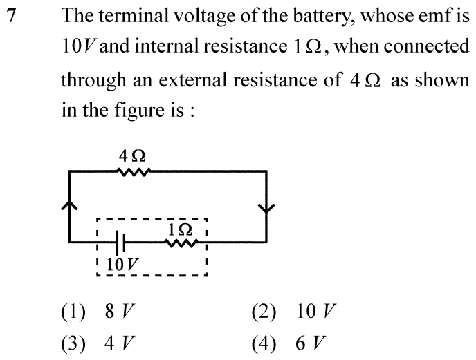
📋 Given Parameters & Problem Setup
Battery EMF E = 10 V
Internal resistance r = 1 Ω
External load resistance R = 4 Ω
⚡

The 30-Second Exam Hall Shortcut: ⚡ Voltage Divider / Terminal Voltage Shortcut

⏱️ Save ~40 seconds

V = E × R / (R + r) = 10 × 4 / (4 + 1) = 40 / 5 = 8 V!

1 Total circuit loop resistance: R_total = R + r = 4 + 1 = 5 Ω.
2 Circuit current: I = E / R_total = 10 / 5 = 2 A.
3 Terminal potential difference across the load: V = I × R = 2 × 4 = 8 V.
4 (Alternatively: V = E - Ir = 10 - 2(1) = 8 V).
5 Option (1) is correct in under 5 seconds!
🛡️
Why You Can 100% Trust This Shortcut: Fundamental Ohm’s Law & Terminal Potential Difference (V = E - Ir = IR).
📐

Step-by-Step Rigorous Workflow & Mathematical Proof

Step 1

Calculation of Total Circuit Current

According to Ohm’s law applied to the complete closed circuit consisting of the real battery and the external resistor, the current is:

I=ER+r=10 V4 Ω+1 Ω=105=2 AI = \frac{E}{R + r} = \frac{10\,\text{V}}{4\,\Omega + 1\,\Omega} = \frac{10}{5} = 2\,\text{A}
Step 2

Determination of Terminal Voltage

During discharge through an external load, the terminal voltage V across the battery terminals is reduced from its open-circuit EMF by the internal voltage drop Ir:

V=E−Ir=10 V−(2 A)(1 Ω)=10−2=8 VV = E - I r = 10\,\text{V} - (2\,\text{A})(1\,\Omega) = 10 - 2 = 8\,\text{V}
Step 3

Cross-Verification Across External Load

The terminal voltage must also identically equal the potential difference across the external 4 Ω resistor:

V=IR=(2 A)(4 Ω)=8 VV = I R = (2\,\text{A})(4\,\Omega) = 8\,\text{V}
⭐

360° Option Elimination Engine Key Feature

Diagnose every choice: Know exactly why the right option works and why distractors fail.

4-Option Deep Scan
1 (1)
✓ 100% Correct
Verdict & Scientific Reason:

Exact terminal voltage: 10 V - 2 V = 8 V.

💡
Why this is airtight: None.
2 (2)
✗ Incorrect
Verdict & Scientific Reason:

This is the open-circuit EMF, ignoring internal resistance drop.

⚠️
Student Fallacy (Why candidates pick this trap): Assuming ideal battery behavior with zero internal resistance.
3 (3)
✗ Incorrect
Verdict & Scientific Reason:

Incorrect; confuses resistance value (4 Ω) with voltage.

⚠️
Student Fallacy (Why candidates pick this trap): Reading the load resistance value directly as voltage.
4 (4)
✗ Incorrect
Verdict & Scientific Reason:

Calculation mistake; occurs if internal resistance drop is miscalculated as 4 V.

⚠️
Student Fallacy (Why candidates pick this trap): Subtracting R from E (10 - 4 = 6) instead of Ir.
⚠️

NTA Trap Alert: Confusing EMF with Terminal Voltage

Candidates often select 10 V, assuming the battery always delivers its rated EMF regardless of the load.

🛡️ How to avoid the -1 mark: Remember: Real battery under load ALWAYS delivers V < E due to internal dissipation Ir.
📖

Core NEET Syllabus Standard

Physics Core Electrodynamics · Current Electricity Standard Benchmark
Core Scientific Principle Tested:

"The terminal voltage across a cell in discharging mode is given by V = E - Ir, where Ir represents the internal ohmic potential drop."

Syllabus Focus: EMF, Internal Resistance and Potential Difference
✓ Core NEET UG Syllabus Anchor Syllabus & Academic Standards ↗
EMF is what the cell CAN make, Terminal Voltage is what you TAKE!
NEET 2024 · Q37 Easy
Official NEET 2024 Question 37 - Current Electricity
1
2
3
4 ✓ Key
💡 Verified Solution & 30-Second Hack
✓
Verified Against NTA Final Answer Key
Option (4) : 2 : 9
📚 Current Electricity Easy
📋 Given Parameters & Problem Setup
Heater A power rating P_A = 1 kW
Heater B power rating P_B = 2 kW
Source voltage Same fixed power source V
⚡

The 30-Second Exam Hall Shortcut: ⚡ Power Reciprocal Product Rule

⏱️ Save ~45 seconds

Series power: 1/P_s = 1/1 + 1/2 = 3/2 -> P_s = 2/3 kW. Parallel power: P_p = 1 + 2 = 3 kW. Ratio P_s / P_p = (2/3) / 3 = 2 : 9!

1 In series across fixed voltage V: 1 / P_series = 1 / P_A + 1 / P_B = 1 / 1 + 1 / 2 = 3/2 => P_series = 2/3 kW.
2 In parallel across fixed voltage V: P_parallel = P_A + P_B = 1 + 2 = 3 kW.
3 Ratio of power outputs: P_series / P_parallel = (2/3) / 3 = 2 / 9 = 2 : 9.
4 Option (4) in 10 seconds!
🛡️
Why You Can 100% Trust This Shortcut: Power Dissipation Formula for Fixed Voltage Source (P_parallel = Σ P_i, 1/P_series = Σ 1/P_i).
📐

Step-by-Step Rigorous Workflow & Mathematical Proof

Step 1

Resistances of Heaters from Rated Power

For a heater designed for rated voltage V, power is P = V² / R, which gives resistance R = V² / P:

RA=V2PA=V21 kW,RB=V2PB=V22 kW=RA2R_A = \frac{V^2}{P_A} = \frac{V^2}{1\,\text{kW}}, \quad R_B = \frac{V^2}{P_B} = \frac{V^2}{2\,\text{kW}} = \frac{R_A}{2}
Step 2

Case 1: Heaters in Series

When connected in series across the same fixed voltage source V, the total equivalent resistance is:

Rseries=RA+RB=RA+RA2=32RAR_{series} = R_A + R_B = R_A + \frac{R_A}{2} = \frac{3}{2} R_A
Step 3

Power Output in Series

The power delivered in the series configuration is:

Pseries=V2Rseries=V232RA=23V2RA=23PA=23 kWP_{series} = \frac{V^2}{R_{series}} = \frac{V^2}{\frac{3}{2} R_A} = \frac{2}{3} \frac{V^2}{R_A} = \frac{2}{3} P_A = \frac{2}{3}\,\text{kW}
Step 4

Case 2: Heaters in Parallel

When connected in parallel across the same fixed voltage V, each heater has the full source voltage across it. Power outputs add directly:

Pparallel=PA+PB=1 kW+2 kW=3 kWP_{parallel} = P_A + P_B = 1\,\text{kW} + 2\,\text{kW} = 3\,\text{kW}
Step 5

Ratio of Power Outputs

Taking the ratio of the series power to parallel power:

PseriesPparallel=2/3 kW3 kW=29  ⟹  Pseries:Pparallel=2:9\frac{P_{series}}{P_{parallel}} = \frac{2/3\,\text{kW}}{3\,\text{kW}} = \frac{2}{9} \implies P_{series} : P_{parallel} = 2 : 9
⭐

360° Option Elimination Engine Key Feature

Diagnose every choice: Know exactly why the right option works and why distractors fail.

4-Option Deep Scan
1 (1)
✗ Incorrect
Verdict & Scientific Reason:

This is the ratio of the individual heater powers (1 kW : 2 kW).

⚠️
Student Fallacy (Why candidates pick this trap): Confusing individual power ratings with series-to-parallel combination ratio.
2 (2)
✗ Incorrect
Verdict & Scientific Reason:

Represents only P_series in kW, forgetting to divide by P_parallel = 3 kW.

⚠️
Student Fallacy (Why candidates pick this trap): Stopping at P_series = 2/3.
3 (3)
✗ Incorrect
Verdict & Scientific Reason:

Physical impossibility; parallel power is always much greater than series power.

⚠️
Student Fallacy (Why candidates pick this trap): Assuming power is conserved regardless of circuit configuration.
4 (4)
✓ 100% Correct
Verdict & Scientific Reason:

Exact ratio: (2/3) / 3 = 2/9.

💡
Why this is airtight: None.
⚠️

NTA Trap Alert: Power Formulas Inversion Trap

Students frequently remember "P = I²R so series adds", forgetting that current I is drastically reduced in series when connected to a fixed VOLTAGE source.

🛡️ How to avoid the -1 mark: For fixed voltage V: In parallel, powers add directly (P_p = P1 + P2); in series, reciprocal powers add (1/P_s = 1/P1 + 1/P2)!
📖

Core NEET Syllabus Standard

Physics Core Electrodynamics · Current Electricity Standard Benchmark
Core Scientific Principle Tested:

"Across a constant voltage source, P_parallel = P1 + P2 and 1/P_series = 1/P1 + 1/P2."

Syllabus Focus: Electric Power and Heating Effects of Current
✓ Core NEET UG Syllabus Anchor Syllabus & Academic Standards ↗
Series adds reciprocals (2/3); Parallel adds direct (3) -> Ratio is 2 to 9!
NEET 2023 · Q10 Easy
Official NEET 2023 Question 10 - Current Electricity
1
2
3
4 ✓ Key
💡 Verified Solution & 30-Second Hack
✓
Verified Against NTA Final Answer Key
Option (4) : 100 Ω
📚 Current Electricity Easy
📋 Given Parameters & Problem Setup
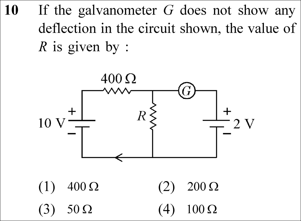
Primary Battery 10 V
Series Primary Resistor 400 Ω
Secondary Null-Balance Battery 2 V
Condition Galvanometer G shows zero deflection (i_g = 0)
⚡

The 30-Second Exam Hall Shortcut: ⚡ Voltage Divider Ratio Mental Shortcut

⏱️ Save ~45 seconds

Zero deflection means voltage across R is exactly 2 V! The 10 V battery splits into 8 V across 400 Ω and 2 V across R. Since 2 V is 1/4th of 8 V, R = 400/4 = 100 Ω in 10 seconds!

1 Null deflection (i_g = 0) means no current enters the galvanometer branch.
2 Therefore, the voltage across resistor R must exactly equal the secondary battery: V_R = 2 V.
3 Since total supply is 10 V, the remaining voltage across the 400 Ω resistor is 10 - 2 = 8 V.
4 By simple proportion of series resistors: R / 400 = V_R / V_400 = 2 / 8 = 1 / 4.
5 R = 400 / 4 = 100 Ω. Instantly pick Option (4)!
🛡️
Why You Can 100% Trust This Shortcut: Fundamental DC Circuit Theory · Kirchhoff's Laws & Voltage Division (Series voltage divider ratio: V₁/V₂ = R₁/R₂).
📐

Step-by-Step Rigorous Workflow & Mathematical Proof

Step 1

Significance of Null Deflection in Galvanometer Branch

When the galvanometer G shows zero deflection, the current flowing through its branch is zero (i_g = 0). By Kirchhoff's Current Law at the junction, the secondary branch is completely isolated in terms of current flow:

ig=0  ⟹  VR=2 Vi_g = 0 \implies V_R = 2\text{ V}
Step 2

Current in the Primary Series Loop

All current from the 10 V source circulates exclusively through the series combination of 400 Ω and R:

I=10400+RI = \frac{10}{400 + R}
Step 3

Voltage Balance across Resistor R

The potential drop across resistor R is given by Ohm's law and must balance the 2 V battery:

VR=I×R=(10400+R)R=2 VV_R = I \times R = \left(\frac{10}{400 + R}\right) R = 2\text{ V}
Step 4

Algebraic Solution for R

Solve the linear equation for resistance R:

10R=2(400+R)  ⟹  10R=800+2R  ⟹  8R=800  ⟹  R=100 Ω10 R = 2(400 + R) \implies 10 R = 800 + 2 R \implies 8 R = 800 \implies R = 100\ \Omega
⭐

360° Option Elimination Engine Key Feature

Diagnose every choice: Know exactly why the right option works and why distractors fail.

4-Option Deep Scan
1 (1)
✗ Incorrect
Verdict & Scientific Reason:

If R were 400 Ω, V_R would be 5 V (half of 10 V), creating a 3 V unbalance across the 2 V cell.

⚠️
Student Fallacy (Why candidates pick this trap): Candidate assumed symmetrical resistance division (R = 400 Ω).
2 (2)
✗ Incorrect
Verdict & Scientific Reason:

If R were 200 Ω, V_R = (200/600) × 10 = 3.33 V ≠ 2 V.

⚠️
Student Fallacy (Why candidates pick this trap): Candidate incorrectly multiplied 100 Ω by 2.
3 (3)
✗ Incorrect
Verdict & Scientific Reason:

If R were 50 Ω, V_R = (50/450) × 10 = 1.11 V ≠ 2 V.

⚠️
Student Fallacy (Why candidates pick this trap): Candidate made an arithmetic division slip, dividing 100 Ω by 2.
4 (4)
✓ 100% Correct
Verdict & Scientific Reason:

Accurate value producing exact 2 V drop across R to achieve galvanometer null deflection.

💡
Why this is airtight: None. Candidate correctly applied the potentiometer balance condition.
⚠️

NTA Trap Alert: Applying Wheatstone Bridge Formula in an Unrelated Two-Battery Loop

Some students attempt to treat this circuit as a Wheatstone bridge and search for four ratio arms. This is simply a potentiometer-style null balance circuit.

🛡️ How to avoid the -1 mark: Whenever a galvanometer has a battery in series and shows zero deflection, set the node voltage equal to that battery voltage!
📖

Core NEET Syllabus Standard

National Eligibility cum Entrance Test (NEET UG) · Current Electricity Standard Benchmark
Core Scientific Principle Tested:

"At null balance (i = 0), the branch draws no current and the terminal potential difference across the parallel resistor equals the secondary EMF."

Syllabus Focus: Kirchhoff's Laws and Null Deflection Circuit Analysis
Preserved in Rationalized Curriculum Syllabus & Academic Standards ↗
NEET 2023 · Q18 Easy
Official NEET 2023 Question 18 - Current Electricity
1
2
3
4 ✓ Key
💡 Verified Solution & 30-Second Hack
✓
Verified Against NTA Final Answer Key
Option (4) : Orange
📚 Current Electricity Easy
📋 Given Parameters & Problem Setup
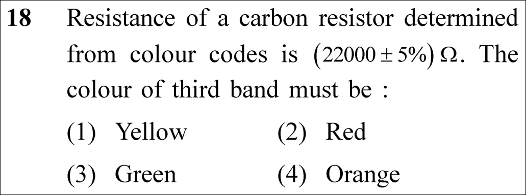
Resistance Value (22000 ± 5%) Ω
Target Band Colour of third band (multiplier band)
⚡

The 30-Second Exam Hall Shortcut: ⚡ BB ROY Great Britain Multiplier Decoder

⏱️ Save ~30 seconds

22000 Ω is 22 × 10³ Ω; the 3rd band represents the power of 10 (10³); in B-B-R-O-Y, 3 corresponds to Orange!

1 Express the resistance in scientific format: 22000 Ω = 22 × 10³ Ω.
2 Identify band roles: 1st digit = 2 (Red), 2nd digit = 2 (Red), 3rd band = multiplier 10ⁿ.
3 The exponent n = 3.
4 Recall the BB ROY mnemonic sequence: Black (0), Brown (1), Red (2), Orange (3), Yellow (4)...
5 Exponent 3 corresponds to Orange.
6 Lock Option (4) Orange in 5 seconds!
🛡️
Why You Can 100% Trust This Shortcut: NCERT Physics · Current Electricity (Resistor colour code standard: R = (AB × 10^C ± D%) Ω where C is multiplier colour).
📐

Step-by-Step Rigorous Workflow & Mathematical Proof

Step 1

Scientific Notation Decomposition of Resistance Value

Standard 4-band carbon resistors encode resistance as R = (AB × 10^C ± D%) Ω, where A and B are the first two significant figures, C is the decimal multiplier, and D is the tolerance percentage:

R=22000 Ω=22×103 Ω±5%R = 22000\ \Omega = 22 \times 10^3\ \Omega \pm 5\%
Step 2

Identification of Significant Figures and Multiplier

Comparing with the standard colour-code format:

A=2 (First band: Red),B=2 (Second band: Red),C=3 (Third band: Multiplier 103)A = 2\text{ (First band: Red)}, \quad B = 2\text{ (Second band: Red)}, \quad C = 3\text{ (Third band: Multiplier } 10^3)
Step 3

Mnemonic Code Verification for Multiplier Digit 3

Using the canonical mnemonic "B B R O Y of Great Britain has Very Good Wife":

Black(0), Brown(1), Red(2), Orange(3), Yellow(4)  ⟹  Third Band=Orange\text{Black}(0), \, \text{Brown}(1), \, \text{Red}(2), \, \mathbf{Orange}(3), \, \text{Yellow}(4) \implies \text{Third Band} = \mathbf{Orange}
⭐

360° Option Elimination Engine Key Feature

Diagnose every choice: Know exactly why the right option works and why distractors fail.

4-Option Deep Scan
1 (1)
✗ Incorrect
Verdict & Scientific Reason:

Yellow corresponds to digit 4 (multiplier 10⁴ = 220,000 Ω).

⚠️
Student Fallacy (Why candidates pick this trap): Candidate miscounted the number of trailing zeroes or counted 2200 as 4 digits.
2 (2)
✗ Incorrect
Verdict & Scientific Reason:

Red corresponds to digit 2 (multiplier 10² = 2200 Ω).

⚠️
Student Fallacy (Why candidates pick this trap): Candidate looked at the first two digits (2, 2) and repeated Red for the third band.
3 (3)
✗ Incorrect
Verdict & Scientific Reason:

Green corresponds to digit 5 (multiplier 10⁵).

⚠️
Student Fallacy (Why candidates pick this trap): Candidate confused the 5% tolerance (gold) with green.
4 (4)
✓ 100% Correct
Verdict & Scientific Reason:

Accurate colour: exponent 3 corresponds to Orange in the BB ROY colour code.

💡
Why this is airtight: None. Candidate correctly factored 22 × 10³.
⚠️

NTA Trap Alert: Counting Total Zeroes vs Multiplier Exponent

The number 22000 has 3 zeroes, meaning the multiplier is 10³, which is Orange. Students who count all zeroes plus the significant digits get confused and pick Yellow.

🛡️ How to avoid the -1 mark: Always rewrite in form: Digit1 Digit2 × 10^(exponent). The exponent directly gives the colour!
📖

Core NEET Syllabus Standard

National Eligibility cum Entrance Test (NEET UG) · Current Electricity Standard Benchmark
Core Scientific Principle Tested:

"First two bands give significant digits, third band gives power of ten multiplier, fourth band gives tolerance."

Syllabus Focus: Resistivity and Colour Code for Carbon Resistors
Historical NEET Benchmark Syllabus & Academic Standards ↗
NEET 2023 · Q28 Easy
Official NEET 2023 Question 28 - Current Electricity
1
2
3 ✓ Key
4
💡 Verified Solution & 30-Second Hack
✓
Verified Against NTA Final Answer Key
Option (3) : 0.5 A from A to B through E
📚 Current Electricity Easy
📋 Given Parameters & Problem Setup
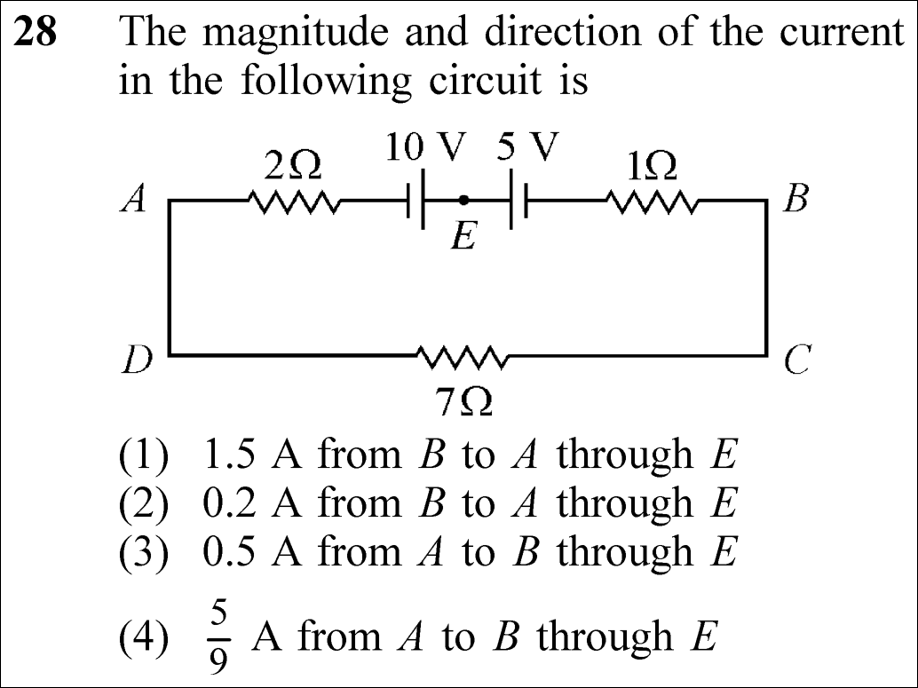
Battery 1 EMF 10 V (connected with 2 Ω internal/series resistance)
Battery 2 EMF 5 V (connected opposing with 1 Ω resistance)
Load Resistor 7 Ω in the lower branch
Total loop resistance (R_tot) 2 Ω + 1 Ω + 7 Ω = 10 Ω
⚡

The 30-Second Exam Hall Shortcut: ⚡ Opposing Cells Net EMF Rule: I = (E₁ - E₂) / ΣR

⏱️ Save ~40 seconds

Net EMF = 10 V - 5 V = 5 V (dominated by 10 V cell). Total resistance = 2 + 1 + 7 = 10 Ω. Current I = 5 / 10 = 0.5 A from A to B through E in 15 seconds!

1 Inspect cell orientations: The 10 V and 5 V batteries oppose each other in the single closed loop.
2 The larger battery (10 V) dictates the net EMF: E_net = 10 V - 5 V = 5 V.
3 Sum all resistors in series around the single loop: R_tot = 2 + 1 + 7 = 10 Ω.
4 Calculate current magnitude: I = E_net / R_tot = 5 V / 10 Ω = 0.5 A.
5 Determine direction: The 10 V battery pushes current out of its positive terminal, which directs current from A to B through point E.
6 Select Option (3) 0.5 A from A to B through E!
🛡️
Why You Can 100% Trust This Shortcut: Current Electricity · Kirchhoff’s Voltage Law (Net current in a single closed loop equals algebraic sum of EMFs divided by total series resistance).
📐

Step-by-Step Rigorous Workflow & Mathematical Proof

Step 1

Circuit Identification and Loop Path

The given circuit is a single closed loop ABCDA. All components (the 2 Ω resistor, the 10 V cell, junction E, the 5 V cell, the 1 Ω resistor, and the 7 Ω resistor) are connected in series.

Rtotal=R1+R2+R3=2 Ω+1 Ω+7 Ω=10 ΩR_{\text{total}} = R_1 + R_2 + R_3 = 2\ \Omega + 1\ \Omega + 7\ \Omega = 10\ \Omega
Step 2

Net Electromotive Force (EMF) in the Loop

The positive terminal of the 10 V source faces towards E (pushing current from left to right, i.e., from A towards B), while the 5 V source faces into E with its positive terminal pushing opposite. Because they are in opposition, the net driving EMF is the difference:

Enet=E1−E2=10 V−5 V=5 VE_{\text{net}} = E_1 - E_2 = 10\text{ V} - 5\text{ V} = 5\text{ V}
Step 3

Calculation of Current Magnitude

By Ohm’s Law / Kirchhoff’s Loop Rule applied to the single closed path:

I=EnetRtotal=5 V10 Ω=0.5 AI = \frac{E_{\text{net}}}{R_{\text{total}}} = \frac{5\text{ V}}{10\ \Omega} = 0.5\text{ A}
Step 4

Determination of Current Direction

Since E₁ (10 V) is greater than E₂ (5 V), the net current flows in the direction driven by the 10 V battery: flowing clockwise through the loop, which corresponds to travelling from A to B through point E.

I=0.5 A(from A to B through E)I = 0.5\text{ A} \quad (\text{from } A \text{ to } B \text{ through } E)
⭐

360° Option Elimination Engine Key Feature

Diagnose every choice: Know exactly why the right option works and why distractors fail.

4-Option Deep Scan
1 (1)
✗ Incorrect
Verdict & Scientific Reason:

Incorrect magnitude and wrong direction (result of adding EMFs 10 + 5 = 15 V).

⚠️
Student Fallacy (Why candidates pick this trap): Candidate erroneously treated the opposing cells as aiding cells (15 V / 10 Ω = 1.5 A).
2 (2)
✗ Incorrect
Verdict & Scientific Reason:

Wrong magnitude and opposite direction.

⚠️
Student Fallacy (Why candidates pick this trap): Candidate inverted the formula or made an arithmetic error.
3 (3)
✓ 100% Correct
Verdict & Scientific Reason:

Accurate magnitude (5 V / 10 Ω = 0.5 A) and correct clockwise direction driven by 10 V battery.

💡
Why this is airtight: None. Candidate correctly identified opposing polarities.
4 (4)
✗ Incorrect
Verdict & Scientific Reason:

Incorrect resistance summation (omitted the 1 Ω internal resistor: 5 / (2 + 7) = 5/9 A).

⚠️
Student Fallacy (Why candidates pick this trap): Candidate forgot the 1 Ω resistor in the loop.
⚠️

NTA Trap Alert: Adding EMFs Instead of Subtracting Opposing Batteries

When two cells face each other positive-to-positive or negative-to-negative, their EMFs oppose each other (Net EMF = 10 - 5 = 5 V). Adding them (10 + 5 = 15 V) yields 1.5 A (Option 1).

🛡️ How to avoid the -1 mark: Trace clockwise: if you exit positive of one cell (+10 V) and exit positive of another (-5 V), they oppose!
📖

Core NEET Syllabus Standard

National Eligibility cum Entrance Test (NEET UG) · Current Electricity Standard Benchmark
Core Scientific Principle Tested:

"In a single series loop, I = ΣE / ΣR, where opposing cells subtract their potentials."

Syllabus Focus: Kirchhoff’s Laws and Grouping of Cells
Preserved in Rationalized Curriculum Syllabus & Academic Standards ↗
NEET 2023 · Q48 Easy
Official NEET 2023 Question 48 - Current Electricity
1
2
3 ✓ Key
4
💡 Verified Solution & 30-Second Hack
✓
Verified Against NTA Final Answer Key
Option (3) : 100
📚 Current Electricity Easy
📋 Given Parameters & Problem Setup
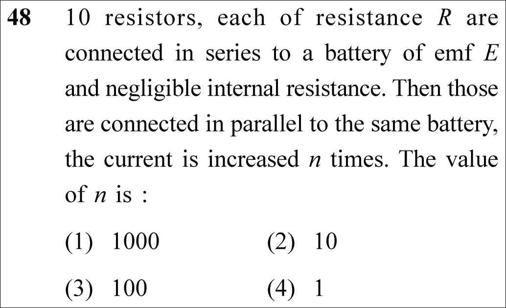
Number of identical resistors (N) 10
Resistance of each resistor R
Battery EMF and internal resistance E, r = 0
Current ratio I_parallel / I_series = n
⚡

The 30-Second Exam Hall Shortcut: ⚡ Series to Parallel Current Scaling: n = N²

⏱️ Save ~35 seconds

R_series = N R and R_parallel = R / N ⟹ I_parallel / I_series = (N R) / (R / N) = N² = 10² = 100 in 5 seconds!

1 Equivalent resistance in series for N identical resistors: R_s = N R = 10 R.
2 Current in series: I_s = E / (10 R).
3 Equivalent resistance in parallel for N identical resistors: R_p = R / N = R / 10.
4 Current in parallel: I_p = E / (R / 10) = 10 E / R.
5 Current magnification factor: n = I_p / I_s = (10 E / R) / (E / 10 R) = 10 × 10 = 100.
6 Lock Option (3) 100 immediately!
🛡️
Why You Can 100% Trust This Shortcut: Current Electricity · Ohm’s Law & Resistor Grouping (Current ratio for N identical resistors between parallel and series across an ideal voltage source is strictly n = N²).
📐

Step-by-Step Rigorous Workflow & Mathematical Proof

Step 1

Series Combination Analysis

When 10 identical resistors of resistance R are connected in series, the equivalent resistance R_s is the direct sum of all individual resistances:

Rs=R+R+⋯+R=10RR_s = R + R + \dots + R = 10 R
Step 2

Current Drawn in Series Configuration

Connected across an ideal battery of EMF E with negligible internal resistance, the circuit current I_s is given by Ohm’s Law:

Is=ERs=E10RI_s = \frac{E}{R_s} = \frac{E}{10 R}
Step 3

Parallel Combination Analysis

When the same 10 resistors are connected in parallel, the reciprocal sum yields equivalent resistance R_p:

1Rp=∑i=1101R=10R  ⟹  Rp=R10\frac{1}{R_p} = \sum_{i=1}^{10} \frac{1}{R} = \frac{10}{R} \implies R_p = \frac{R}{10}
Step 4

Current Drawn in Parallel Configuration

Connected across the same battery of EMF E, the circuit current I_p is:

Ip=ERp=ER10=10ERI_p = \frac{E}{R_p} = \frac{E}{\frac{R}{10}} = \frac{10 E}{R}
Step 5

Evaluation of Current Multiplication Factor n

The problem states that I_p = n I_s. Taking the ratio:

n=IpIs=10ERE10R=10×10=100n = \frac{I_p}{I_s} = \frac{\frac{10 E}{R}}{\frac{E}{10 R}} = 10 \times 10 = 100
⭐

360° Option Elimination Engine Key Feature

Diagnose every choice: Know exactly why the right option works and why distractors fail.

4-Option Deep Scan
1 (1)
✗ Incorrect
Verdict & Scientific Reason:

Overestimates by a factor of 10 (N³ instead of N²).

⚠️
Student Fallacy (Why candidates pick this trap): Candidate computed 10³ = 1000.
2 (2)
✗ Incorrect
Verdict & Scientific Reason:

Current in each individual parallel branch increases by 1, or candidate thought n = N.

⚠️
Student Fallacy (Why candidates pick this trap): Candidate assumed current increases by N = 10 times instead of N² = 100.
3 (3)
✓ 100% Correct
Verdict & Scientific Reason:

Accurate multiplication factor: n = N² = 10² = 100.

💡
Why this is airtight: None. Candidate correctly recognized the N² ratio.
4 (4)
✗ Incorrect
Verdict & Scientific Reason:

Absurd claim that current remains unchanged.

⚠️
Student Fallacy (Why candidates pick this trap): Candidate confused power with current or made a wild guess.
⚠️

NTA Trap Alert: Thinking Current Increases by N = 10 Times Instead of N² = 100 Times

In parallel, each branch draws E/R (which is 10× the series current E/10R). Since there are 10 parallel branches, the TOTAL battery current is 10 × (10 E/10R) = 100 × I_series! Confusing branch current with total current leads to Option (2) 10.

🛡️ How to avoid the -1 mark: Universal Rule: For N identical resistors, R_s / R_p = N² ⟹ I_p / I_s = N².
📖

Core NEET Syllabus Standard

National Eligibility cum Entrance Test (NEET UG) · Current Electricity Standard Benchmark
Core Scientific Principle Tested:

"Series resistance is N R; parallel resistance is R/N. Current ratio across constant voltage is N²."

Syllabus Focus: Resistors in Series and Parallel
Preserved in Rationalized Curriculum Syllabus & Academic Standards ↗
NEET 2023 · Q50 Easy
Official NEET 2023 Question 50 - Current Electricity
1
2
3
4 ✓ Key
💡 Verified Solution & 30-Second Hack
✓
Verified Against NTA Final Answer Key
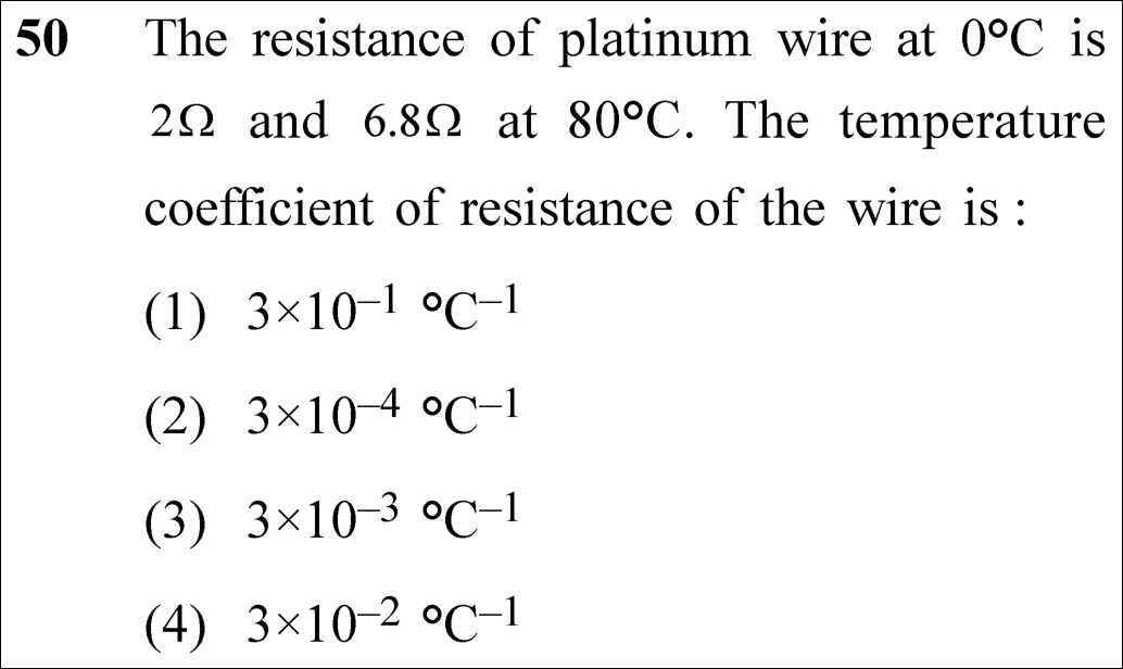
Option (4) : 3 × 10⁻² °C⁻¹
📚 Current Electricity Easy
📋 Given Parameters & Problem Setup
Resistance at 0°C (R₀) 2 Ω
Resistance at 80°C (R_t) 6.8 Ω
Temperature difference (ΔT) 80°C - 0°C = 80°C
Governing relation R_t = R₀ (1 + α ΔT)
⚡

The 30-Second Exam Hall Shortcut: ⚡ Direct Slope Formula: α = ΔR / (R₀ · ΔT)

⏱️ Save ~35 seconds

ΔR = 6.8 - 2 = 4.8 Ω. Then α = 4.8 / (2 × 80) = 4.8 / 160 = 48 / 1600 = 3 / 100 = 3 × 10⁻² °C⁻¹ in 10 seconds!

1 Formula for temperature variation of resistance: R_t = R₀(1 + α ΔT).
2 Rearrange for temperature coefficient: α = (R_t - R₀) / (R₀ ΔT) = ΔR / (R₀ ΔT).
3 Calculate resistance change: ΔR = 6.8 Ω - 2 Ω = 4.8 Ω.
4 Substitute values: α = 4.8 / (2 × 80) = 4.8 / 160.
5 Simplify fraction: 4.8 / 160 = 48 / 1600 = 3 / 100 = 0.03 = 3 × 10⁻² °C⁻¹.
6 Lock Option (4) 3 × 10⁻² °C⁻¹ instantly!
🛡️
Why You Can 100% Trust This Shortcut: Current Electricity · Temperature Dependence of Resistance (α is defined as fractional change in resistance per unit temperature rise: α = ΔR / (R₀ · ΔT)).
📐

Step-by-Step Rigorous Workflow & Mathematical Proof

Step 1

Governing Formula for Temperature Dependence of Resistance

Over moderate temperature intervals, the electrical resistance of a metallic conductor varies linearly with temperature according to the relation:

Rt=R0(1+αΔT)R_t = R_0 (1 + \alpha \Delta T)
Step 2

Identification of Given Parameters

From the problem statement:

R0=2 Ω,Rt=6.8 Ω,ΔT=80∘C−0∘C=80∘CR_0 = 2\ \Omega, \quad R_t = 6.8\ \Omega, \quad \Delta T = 80^\circ\text{C} - 0^\circ\text{C} = 80^\circ\text{C}
Step 3

Rearrangement for Temperature Coefficient α

Expanding and isolating the temperature coefficient α:

Rt−R0=R0αΔT  ⟹  α=Rt−R0R0ΔTR_t - R_0 = R_0 \alpha \Delta T \implies \alpha = \frac{R_t - R_0}{R_0 \Delta T}
Step 4

Substitution and Numerical Evaluation

Substitute the given values into the isolated equation:

α=6.8−22×80=4.8160=481600=3100=0.03 ∘C−1\alpha = \frac{6.8 - 2}{2 \times 80} = \frac{4.8}{160} = \frac{48}{1600} = \frac{3}{100} = 0.03\ ^\circ\text{C}^{-1}
Step 5

Expression in Standard Scientific Notation

Convert 0.03 to scientific notation:

α=3×10⁻² ∘C−1\alpha = 3 \times 10^{-2}\ ^\circ\text{C}^{-1}
⭐

360° Option Elimination Engine Key Feature

Diagnose every choice: Know exactly why the right option works and why distractors fail.

4-Option Deep Scan
1 (1)
✗ Incorrect
Verdict & Scientific Reason:

Off by a factor of 10 (0.3 instead of 0.03).

⚠️
Student Fallacy (Why candidates pick this trap): Candidate divided 4.8 by 16 instead of 160.
2 (2)
✗ Incorrect
Verdict & Scientific Reason:

Underestimates coefficient by a factor of 100.

⚠️
Student Fallacy (Why candidates pick this trap): Candidate placed two extra zeros in the denominator.
3 (3)
✗ Incorrect
Verdict & Scientific Reason:

Typical platinum wire value in textbooks (3.9 × 10⁻³), but does NOT match the exam question’s specific numbers.

⚠️
Student Fallacy (Why candidates pick this trap): Candidate guessed based on standard textbook platinum value without doing the math.
4 (4)
✓ 100% Correct
Verdict & Scientific Reason:

Accurate value derived from given data: 4.8 / 160 = 0.03 = 3 × 10⁻² °C⁻¹.

💡
Why this is airtight: None. Candidate executed the calculation accurately.
⚠️

NTA Trap Alert: Blindly Selecting Standard Textbook Value (3.9 × 10⁻³ °C⁻¹)

Students who memorize standard physical constants often know that platinum has α ≈ 3.9 × 10⁻³ °C⁻¹ and hastily select Option (3) 3 × 10⁻³. The exam question uses hypothetical numbers (R increases from 2 Ω to 6.8 Ω over only 80°C!), yielding α = 0.03 = 3 × 10⁻² °C⁻¹.

🛡️ How to avoid the -1 mark: Never guess based on real-world constants; always calculate from the numbers given in the question!
📖

Core NEET Syllabus Standard

National Eligibility cum Entrance Test (NEET UG) · Current Electricity Standard Benchmark
Core Scientific Principle Tested:

"Temperature coefficient of resistance is α = ΔR / (R₀ ΔT)."

Syllabus Focus: Temperature Dependence of Resistivity and Resistance
Preserved in Rationalized Curriculum Syllabus & Academic Standards ↗
NEET 2021 · Q12 Easy
Official NEET 2021 Question 12 - Current Electricity
1 ✓ Key
2
3
4
💡 Verified Solution & 30-Second Hack
✓
Verified Against NTA Final Answer Key
Option (1) : (A)-(R), (B)-(S), (C)-(P), (D)-(Q)
📚 Current Electricity Easy
📋 Given Parameters & Problem Setup
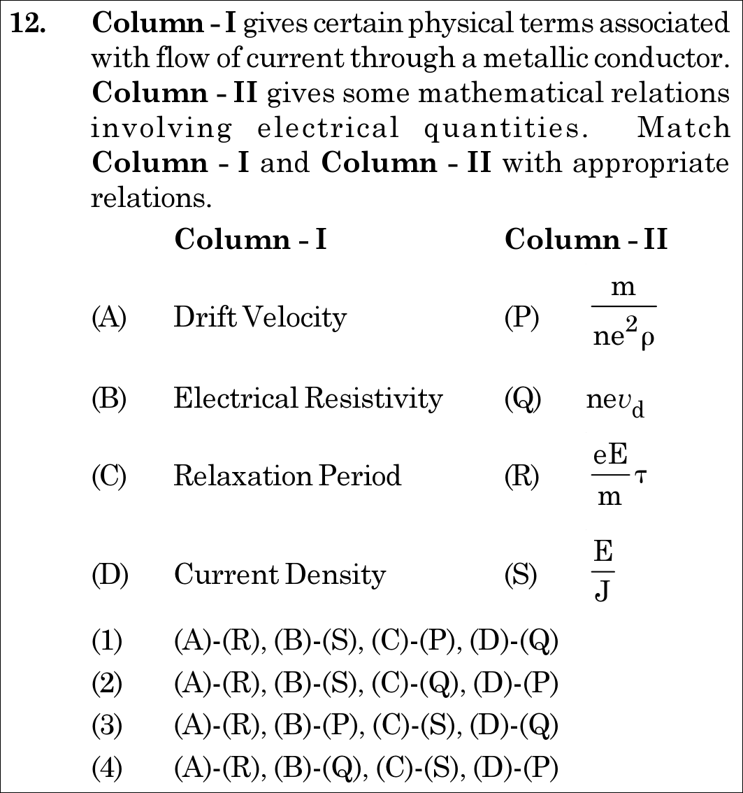
Column I (A) Drift Velocity, (B) Electrical Resistivity, (C) Relaxation Period, (D) Current Density
Column II (P) m / (n e^2 ρ), (Q) n e v_d, (R) e E τ / m, (S) E / J
⚡

The 30-Second Exam Hall Shortcut: ⚡ Microscopic Formula Matcher

⏱️ Save ~25 seconds

Match standard NCERT microscopic expressions: Drift velocity vd=eEmτv_d = \frac{eE}{m}\tau (R); Resistivity ρ=EJ\rho = \frac{E}{J} (S); Current density J=nevdJ = n e v_d (Q); Relaxation time τ=mne2ρ\tau = \frac{m}{n e^2 \rho} (P)! Instant 10-second match to Option (1)!

1 Drift velocity formula: vd=eEmτ  ⟹  (A)−(R)v_d = \frac{eE}{m}\tau \implies (A)-(R).
2 Ohm's law in microscopic form: E=ρJ  ⟹  ρ=EJ  ⟹  (B)−(S)E = \rho J \implies \rho = \frac{E}{J} \implies (B)-(S).
3 Current density formula: J=IA=nevd  ⟹  (D)−(Q)J = \frac{I}{A} = n e v_d \implies (D)-(Q).
4 Relaxation time: from ρ=mne2τ  ⟹  τ=mne2ρ  ⟹  (C)−(P)\rho = \frac{m}{n e^2 \tau} \implies \tau = \frac{m}{n e^2 \rho} \implies (C)-(P).
5 Match combination: (A)-(R), (B)-(S), (C)-(P), (D)-(Q) -> Option (1).
🛡️
Why You Can 100% Trust This Shortcut: Canonical Drude-Lorentz free electron theory and microscopic Ohm's law.
📐

Step-by-Step Rigorous Workflow & Mathematical Proof

Step 1

Formula for Drift Velocity (A)

Under an applied electric field E⃗\vec{E}, the electric force on an electron is −eE⃗-e\vec{E}, imparting acceleration a⃗=−eE⃗/m\vec{a} = -e\vec{E}/m. The average velocity acquired over relaxation time τ\tau is:

vd=aτ=eEmτ  ⟹  (A)−(R)v_d = a\tau = \frac{eE}{m}\tau \implies \mathbf{(A)-(R)}
Step 2

Formula for Electrical Resistivity (B)

In vector microscopic notation, Ohm's law states J⃗=σE⃗=1ρE⃗\vec{J} = \sigma \vec{E} = \frac{1}{\rho}\vec{E}. Rearranging gives electrical resistivity:

ρ=EJ  ⟹  (B)−(S)\rho = \frac{E}{J} \implies \mathbf{(B)-(S)}
Step 3

Formula for Current Density (D)

Electric current is I=neAvdI = n e A v_d. Dividing by cross-sectional area AA gives the current density:

J=IA=nevd  ⟹  (D)−(Q)J = \frac{I}{A} = n e v_d \implies \mathbf{(D)-(Q)}
Step 4

Formula for Relaxation Period (C)

Microscopic resistivity in terms of electron mass mm, charge ee, number density nn, and relaxation time τ\tau is ρ=mne2τ\rho = \frac{m}{n e^2 \tau}. Solving for τ\tau gives:

τ=mne2ρ  ⟹  (C)−(P)\tau = \frac{m}{n e^2 \rho} \implies \mathbf{(C)-(P)}
⭐

360° Option Elimination Engine Key Feature

Diagnose every choice: Know exactly why the right option works and why distractors fail.

4-Option Deep Scan
1 1
✓ 100% Correct
Verdict & Scientific Reason:

Flawless 1-to-1 correspondence with the canonical NCERT microscopic current equations.

💡
Why this is airtight: None; textbook verbatim matching.
2 2
✗ Incorrect
Verdict & Scientific Reason:

Swaps relaxation period (C) and current density (D).

⚠️
Student Fallacy (Why candidates pick this trap): Mismatched (C) and (D).
3 3
✗ Incorrect
Verdict & Scientific Reason:

Mismatches resistivity (B) with formula for relaxation period.

⚠️
Student Fallacy (Why candidates pick this trap): Confusing ρ\rho and τ\tau.
4 4
✗ Incorrect
Verdict & Scientific Reason:

Scrambles multiple associations.

⚠️
Student Fallacy (Why candidates pick this trap): Random pairing.
⚠️

NTA Trap Alert: Relaxation Time Inversion Trap

Students frequently remember ρ=mne2τ\rho = \frac{m}{n e^2 \tau} and get confused when Column II presents τ=mne2ρ\tau = \frac{m}{n e^2 \rho}, mistaking it for resistivity.

🛡️ How to avoid the -1 mark: Cross-multiply: τ=mne2ρ\tau = \frac{m}{n e^2 \rho}. It matches Relaxation Period directly.
📖

Core NEET Syllabus Standard

NCERT Physics · Current Electricity Standard Benchmark
Core Scientific Principle Tested:

"Drift velocity is vd=eEmτv_d = \frac{eE}{m}\tau, current density is J=nevdJ = n e v_d, and resistivity is ρ=EJ=mne2τ\rho = \frac{E}{J} = \frac{m}{n e^2 \tau}."

Syllabus Focus: Drift of Electrons and the Origin of Resistivity
✓ Core NEET UG Syllabus Anchor Syllabus & Academic Standards ↗
NEET 2021 · Q18 Easy
Official NEET 2021 Question 18 - Current Electricity
1
2
3
4 ✓ Key
💡 Verified Solution & 30-Second Hack
✓
Verified Against NTA Final Answer Key
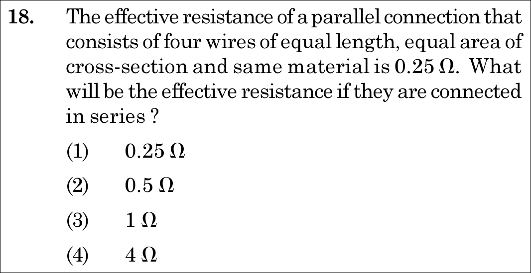
Option (4) : 4 Ω
📚 Current Electricity Easy
📋 Given Parameters & Problem Setup
Number of Identical Wires (n) 4
Effective Parallel Resistance (R_p) 0.25 Ω
⚡

The 30-Second Exam Hall Shortcut: ⚡ The n² Ratio Shortcut: R_s = n² R_p

⏱️ Save ~20 seconds

For nn identical resistors, Rp=R/nR_p = R/n and Rs=nR  ⟹  Rs/Rp=n2R_s = n R \implies R_s / R_p = n^2. Here n=4n = 4, so Rs=42×Rp=16×0.25=4 ΩR_s = 4^2 \times R_p = 16 \times 0.25 = 4\ \Omega! Instant 5-second calculation matching Option (4)!

1 Recall universal relation for nn identical resistors: Rs=n2RpR_s = n^2 R_p.
2 Here n=4n = 4 and Rp=0.25 Ω=1/4 ΩR_p = 0.25\ \Omega = 1/4\ \Omega.
3 Substitute: Rs=42×14=16×14=4 ΩR_s = 4^2 \times \frac{1}{4} = 16 \times \frac{1}{4} = 4\ \Omega.
4 Match Option (4).
🛡️
Why You Can 100% Trust This Shortcut: Canonical Ohm's law rules for series and parallel networks.
📐

Step-by-Step Rigorous Workflow & Mathematical Proof

Step 1

Determining Resistance of an Individual Wire

Since the four wires have identical length ll, area AA, and resistivity ρ\rho, each wire has the same resistance R=ρl/AR = \rho l / A. When connected in parallel, their equivalent resistance RpR_p is:

1Rp=1R+1R+1R+1R=4R  ⟹  Rp=R4\frac{1}{R_p} = \frac{1}{R} + \frac{1}{R} + \frac{1}{R} + \frac{1}{R} = \frac{4}{R} \implies R_p = \frac{R}{4}
Step 2

Calculating the Individual Resistance R

Given Rp=0.25 ΩR_p = 0.25\ \Omega:

R=4×Rp=4×0.25 Ω=1.0 ΩR = 4 \times R_p = 4 \times 0.25\ \Omega = 1.0\ \Omega
Step 3

Calculating Equivalent Resistance in Series (R_s)

When the four identical wires of resistance R=1.0 ΩR = 1.0\ \Omega are connected in series:

Rs=R+R+R+R=4R=4×1.0 Ω=4.0 ΩR_s = R + R + R + R = 4R = 4 \times 1.0\ \Omega = 4.0\ \Omega
⭐

360° Option Elimination Engine Key Feature

Diagnose every choice: Know exactly why the right option works and why distractors fail.

4-Option Deep Scan
1 1
✗ Incorrect
Verdict & Scientific Reason:

This is the parallel resistance (RpR_p), not the series resistance.

⚠️
Student Fallacy (Why candidates pick this trap): Assuming series and parallel configurations yield identical resistance.
2 2
✗ Incorrect
Verdict & Scientific Reason:

Result of doubling instead of applying n2=16n^2 = 16 multiplier.

⚠️
Student Fallacy (Why candidates pick this trap): Incorrect proportionality factor.
3 3
✗ Incorrect
Verdict & Scientific Reason:

This is the resistance of a single wire (R=1 ΩR = 1\ \Omega), not the four wires in series.

⚠️
Student Fallacy (Why candidates pick this trap): Finding individual resistance and forgetting to multiply by n=4n = 4 for series connection.
4 4
✓ 100% Correct
Verdict & Scientific Reason:

Exact series equivalent resistance: Rs=n2Rp=16×0.25=4 ΩR_s = n^2 R_p = 16 \times 0.25 = 4\ \Omega.

💡
Why this is airtight: None; flawless resistor network computation.
⚠️

NTA Trap Alert: Individual Resistor vs. Series Network Trap

Students frequently compute R=4×0.25=1 ΩR = 4 \times 0.25 = 1\ \Omega and immediately select Option (3) 1 Ω1\ \Omega, forgetting that the question asks for all four connected in series (Rs=4×1=4 ΩR_s = 4 \times 1 = 4\ \Omega).

🛡️ How to avoid the -1 mark: Use the master ratio Rs=n2RpR_s = n^2 R_p directly to avoid stopping at single-resistor intermediate steps.
📖

Core NEET Syllabus Standard

NCERT Physics · Current Electricity Standard Benchmark
Core Scientific Principle Tested:

"For nn identical resistors, Rs=nRR_s = n R and Rp=R/nR_p = R/n, giving the universal ratio Rs/Rp=n2R_s / R_p = n^2."

Syllabus Focus: Combination of Resistors - Series and Parallel
✓ Core NEET UG Syllabus Anchor Syllabus & Academic Standards ↗
NEET 2021 · Q19 Easy
Official NEET 2021 Question 19 - Current Electricity
1 ✓ Key
2
3
4
💡 Verified Solution & 30-Second Hack
✓
Verified Against NTA Final Answer Key
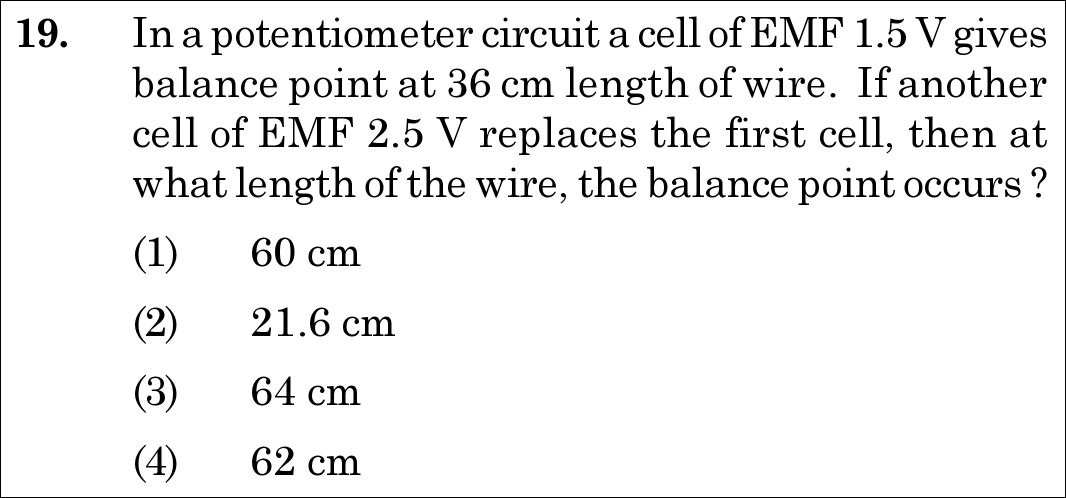
Option (1) : 60 cm
📚 Current Electricity Easy
📋 Given Parameters & Problem Setup
Initial Cell EMF (E_1) 1.5 V
Initial Balancing Length (l_1) 36 cm
Replacement Cell EMF (E_2) 2.5 V
⚡

The 30-Second Exam Hall Shortcut: ⚡ Potentiometer Ratio Rule: l2 = l1 × (E2 / E1)

⏱️ Save ~20 seconds

Potential gradient is constant along the wire, so balancing length is strictly proportional to EMF: l∝El \propto E. Therefore, l2=36×2.51.5=36×53=12×5=60 cml_2 = 36 \times \frac{2.5}{1.5} = 36 \times \frac{5}{3} = 12 \times 5 = 60\text{ cm}! Instant 10-second calculation matching Option (1)!

1 Principle of potentiometer: E∝l  ⟹  E1E2=l1l2E \propto l \implies \frac{E_1}{E_2} = \frac{l_1}{l_2}.
2 Express l2l_2: l2=l1(E2E1)l_2 = l_1 \left(\frac{E_2}{E_1}\right).
3 Substitute: l2=36 cm×(2.5 V1.5 V)=36×53l_2 = 36\text{ cm} \times \left(\frac{2.5\text{ V}}{1.5\text{ V}}\right) = 36 \times \frac{5}{3}.
4 l2=60 cml_2 = 60\text{ cm}.
5 Match Option (1).
🛡️
Why You Can 100% Trust This Shortcut: Canonical potentiometer null deflection voltage-length proportionality.
📐

Step-by-Step Rigorous Workflow & Mathematical Proof

Step 1

Formulating the Principle of a Potentiometer

For a uniform potentiometer wire carrying a steady current, the potential drop per unit length (potential gradient kk) is constant. At null deflection, the EMF of the test cell is balanced by the potential drop across balancing length ll:

E=k⋅l  ⟹  E∝lE = k \cdot l \implies E \propto l
Step 2

Setting Up the Proportionality Ratio

Comparing the two test cells balanced on the same potentiometer wire:

E1E2=l1l2  ⟹  l2=l1(E2E1)\frac{E_1}{E_2} = \frac{l_1}{l_2} \implies l_2 = l_1 \left(\frac{E_2}{E_1}\right)
Step 3

Substituting Given Numerical Values

Substitute l1=36 cml_1 = 36\text{ cm}, E1=1.5 VE_1 = 1.5\text{ V}, and E2=2.5 VE_2 = 2.5\text{ V}:

l2=36 cm×2.51.5=36×53=60 cml_2 = 36\text{ cm} \times \frac{2.5}{1.5} = 36 \times \frac{5}{3} = 60\text{ cm}
⭐

360° Option Elimination Engine Key Feature

Diagnose every choice: Know exactly why the right option works and why distractors fail.

4-Option Deep Scan
1 1
✓ 100% Correct
Verdict & Scientific Reason:

Exact balancing length for the 2.5 V cell: 36×(5/3)=60 cm36 \times (5/3) = 60\text{ cm}.

💡
Why this is airtight: None; textbook potentiometer derivation.
2 2
✗ Incorrect
Verdict & Scientific Reason:

Result of inverting the EMF ratio: 36×(1.5/2.5)=21.6 cm36 \times (1.5 / 2.5) = 21.6\text{ cm} (a higher EMF must produce a LARGER balancing length).

⚠️
Student Fallacy (Why candidates pick this trap): Inverting the ratio E1/E2E_1 / E_2.
3 3
✗ Incorrect
Verdict & Scientific Reason:

Arithmetic approximation error.

⚠️
Student Fallacy (Why candidates pick this trap): Rough estimation without exact calculation.
4 4
✗ Incorrect
Verdict & Scientific Reason:

Calculation error.

⚠️
Student Fallacy (Why candidates pick this trap): Rounding error.
⚠️

NTA Trap Alert: Inverted Ratio Trap

Students who accidentally multiply by E1/E2E_1 / E_2 obtain 21.6 cm21.6\text{ cm}, which NTA intentionally provided as Option (2). Since 2.5 V>1.5 V2.5\text{ V} > 1.5\text{ V}, the balancing length MUST be longer than 36 cm36\text{ cm}.

🛡️ How to avoid the -1 mark: Sanity check: Larger EMF requires a LONGER length to balance. l2>36 cml_2 > 36\text{ cm} immediately eliminates Option (2).
📖

Core NEET Syllabus Standard

NCERT Physics · Current Electricity Standard Benchmark
Core Scientific Principle Tested:

"In a potentiometer circuit, balancing length is directly proportional to the cell EMF: E1/E2=l1/l2E_1 / E_2 = l_1 / l_2."

Syllabus Focus: Potentiometer (Comparison of EMF of Two Cells)
✓ Core NEET UG Syllabus Anchor Syllabus & Academic Standards ↗
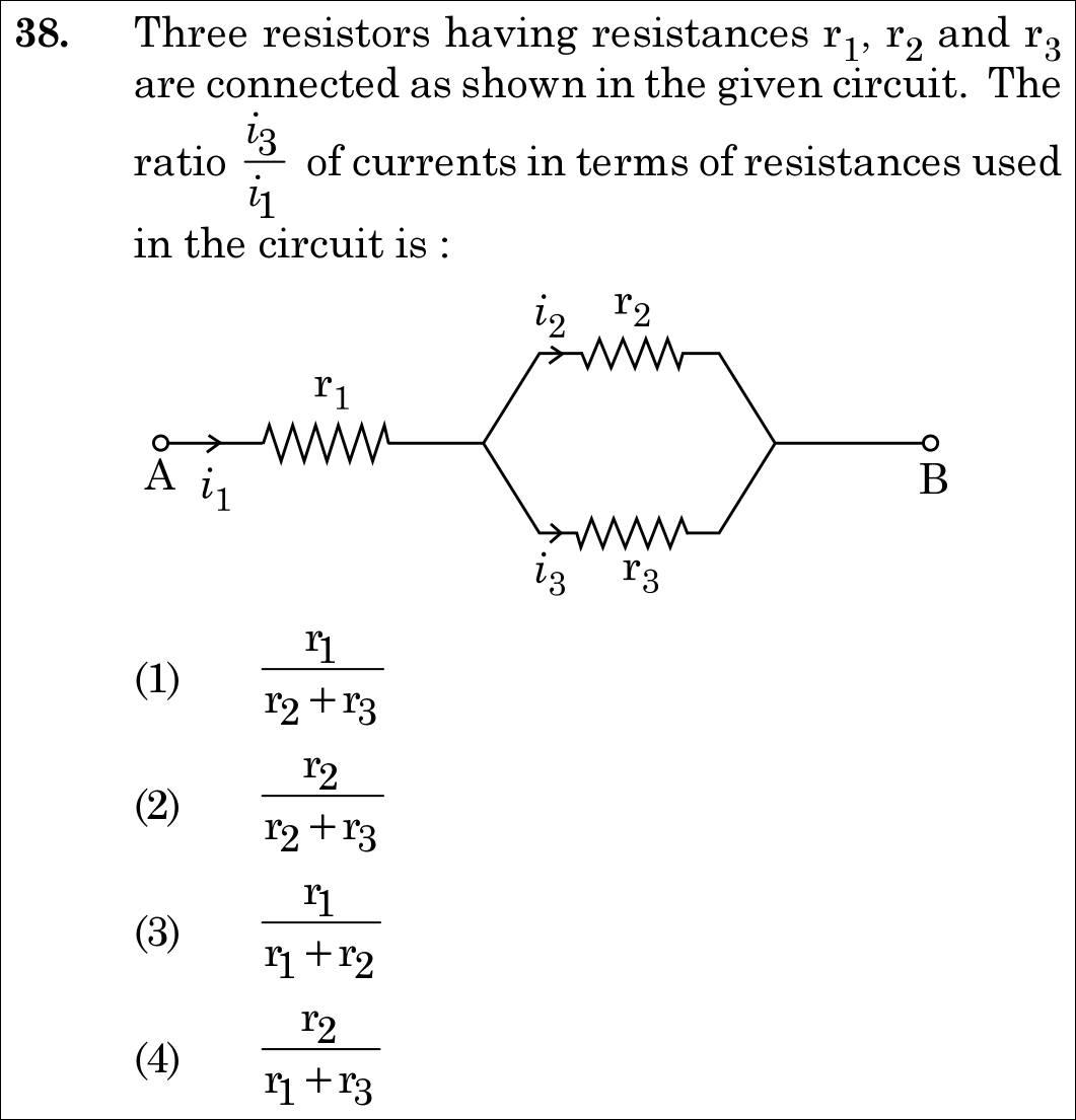
NEET 2021 · Q38 Easy
Official NEET 2021 Question 38 - Current Electricity
1 r r r +
2 r r r + ✓ Key
3 r r r +
4 r r r +
💡 Verified Solution & 30-Second Hack
✓
Verified Against NTA Final Answer Key
Option (2) : r2 / (r2 + r3)
📚 Current Electricity Easy
📋 Given Parameters & Problem Setup
Total Current entering network i_1
Branch Resistor 2 r_2 (current i_2)
Branch Resistor 3 r_3 (current i_3)
Series Resistor r_1 (carries full current i_1)
⚡

The 30-Second Exam Hall Shortcut: ⚡ Inverse Resistance Current Divider Rule

⏱️ Save ~20 seconds

By Kirchhoff's junction rule, total current entering parallel branches is i1=i2+i3i_1 = i_2 + i_3. Parallel branches share identical voltage (i2r2=i3r3i_2 r_2 = i_3 r_3). The fraction of current flowing through branch 3 is inversely proportional to r3r_3: i3=i1r2r2+r3  ⟹  i3i1=r2r2+r3i_3 = i_1 \frac{r_2}{r_2 + r_3} \implies \frac{i_3}{i_1} = \frac{r_2}{r_2 + r_3}! Instant 5-second answer matching Option (2)!

1 Total current i1i_1 flows through r1r_1 and then splits into branches r2r_2 and r3r_3: i1=i2+i3i_1 = i_2 + i_3.
2 Since branches r2r_2 and r3r_3 are in parallel, voltage across them is equal: Vp=i2r2=i3r3V_p = i_2 r_2 = i_3 r_3.
3 Substitute i2=i1−i3i_2 = i_1 - i_3: (i1−i3)r2=i3r3  ⟹  i1r2=i3(r2+r3)(i_1 - i_3) r_2 = i_3 r_3 \implies i_1 r_2 = i_3 (r_2 + r_3).
4 Divide by i1i_1: i3i1=r2r2+r3\frac{i_3}{i_1} = \frac{r_2}{r_2 + r_3}.
5 Match Option (2).
🛡️
Why You Can 100% Trust This Shortcut: Canonical current division rule for two parallel resistors.
📐

Step-by-Step Rigorous Workflow & Mathematical Proof

Step 1

Applying Kirchhoff's Current Law (KCL)

Current i1i_1 enters from terminal A and passes entirely through resistor r1r_1. At the junction ahead of r1r_1, the current divides into two parallel branches containing r2r_2 and r3r_3:

i1=i2+i3  ⟹  i2=i1−i3i_1 = i_2 + i_3 \implies i_2 = i_1 - i_3
Step 2

Equating Potential Difference Across Parallel Branches

Because resistors r2r_2 and r3r_3 are connected across the exact same pair of nodes, their potential drops are equal:

V2=V3  ⟹  i2r2=i3r3V_2 = V_3 \implies i_2 r_2 = i_3 r_3
Step 3

Solving for the Current Ratio i3 / i1

Substitute i2=i1−i3i_2 = i_1 - i_3 into the voltage equality equation:

(i1−i3)r2=i3r3  ⟹  i1r2−i3r2=i3r3  ⟹  i1r2=i3(r2+r3)  ⟹  i3i1=r2r2+r3(i_1 - i_3) r_2 = i_3 r_3 \implies i_1 r_2 - i_3 r_2 = i_3 r_3 \implies i_1 r_2 = i_3 (r_2 + r_3) \implies \frac{i_3}{i_1} = \frac{r_2}{r_2 + r_3}
⭐

360° Option Elimination Engine Key Feature

Diagnose every choice: Know exactly why the right option works and why distractors fail.

4-Option Deep Scan
1 1
✗ Incorrect
Verdict & Scientific Reason:

Inappropriately includes r1r_1, which is in series and does not participate in the parallel current division.

⚠️
Student Fallacy (Why candidates pick this trap): Assuming the series resistor determines branch current splitting.
2 2
✓ 100% Correct
Verdict & Scientific Reason:

Exact current divider formula for branch r3r_3 (i3/i1=r2/(r2+r3)i_3 / i_1 = r_2 / (r_2 + r_3)).

💡
Why this is airtight: None; textbook circuit law.
3 3
✗ Incorrect
Verdict & Scientific Reason:

Omits r3r_3 completely.

⚠️
Student Fallacy (Why candidates pick this trap): Mismatched resistor labels.
4 4
✗ Incorrect
Verdict & Scientific Reason:

Replaces r2r_2 in denominator with series resistance r1r_1.

⚠️
Student Fallacy (Why candidates pick this trap): Treating r1r_1 and r3r_3 as the parallel pair.
⚠️

NTA Trap Alert: Opposite Resistor Rule in Current Divider Trap

In a current divider, the current in branch 3 (i3i_3) depends on the OPPOSITE branch resistance r2r_2 in the numerator: i3∝r2r2+r3i_3 \propto \frac{r_2}{r_2 + r_3}. Students often mistakenly place r3r_3 in the numerator.

🛡️ How to avoid the -1 mark: Higher resistance draws LESS current! Hence i3i_3 must have the other resistor (r2r_2) in the numerator.
📖

Core NEET Syllabus Standard

NCERT Physics · Current Electricity Standard Benchmark
Core Scientific Principle Tested:

"In parallel branches, current divides inversely proportional to resistance: i3=i1r2r2+r3i_3 = i_1 \frac{r_2}{r_2 + r_3}."

Syllabus Focus: Kirchhoff's Rules and Current Division
✓ Core NEET UG Syllabus Anchor Syllabus & Academic Standards ↗
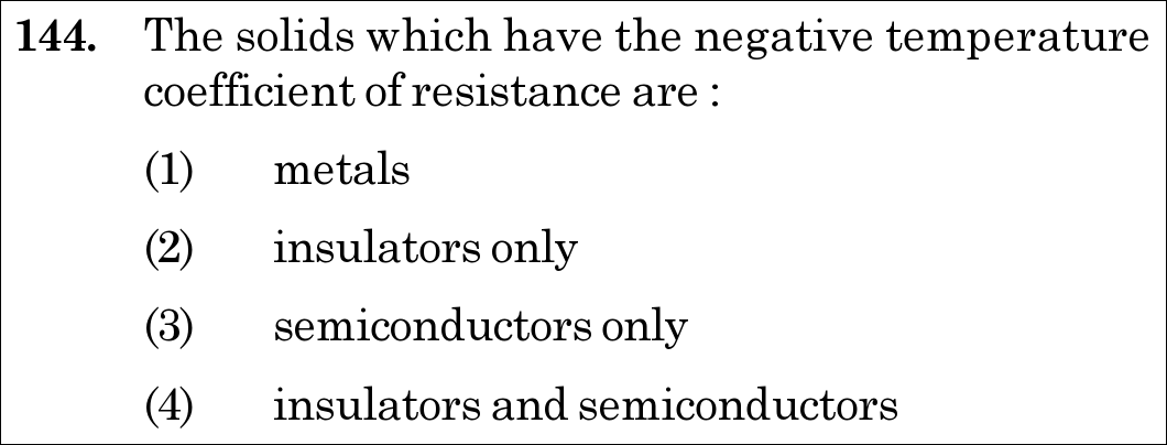
NEET 2020 · Q144 Easy
Official NEET 2020 Question 144 - Current Electricity
1 metals
2 insulators only
3 semiconductors only
4 insulators and semiconductors ✓ Key
💡 Verified Solution & 30-Second Hack
✓
Verified Against NTA Final Answer Key
Option (4) : insulators and semiconductors
📚 Current Electricity Easy
📋 Given Parameters & Problem Setup
Physical Property Temperature coefficient of resistance (α)
Condition Negative temperature coefficient (α < 0, resistance decreases as temperature increases)
Solid Classes Metals, Insulators, Semiconductors
⚡

The 30-Second Exam Hall Shortcut: ⚡ "Metals Have Positive α (R increases with T); Insulators and Semiconductors Have Negative α (R decreases with T)!"

⏱️ 20 seconds

In metallic conductors, heating increases lattice vibrations and collision frequency, so resistance increases (α>0\alpha > 0). In semiconductors and insulators, heating breaks covalent bonds, exponentially increasing the charge carrier density (nn). Because ρ=mne2τ\rho = \frac{m}{n e^2 \tau}, the massive rise in nn dominates over the slight drop in τ\tau, causing resistance to drop sharply with temperature (α<0\alpha < 0). Hence, BOTH insulators and semiconductors have negative α\alpha! Mark Option (4) in 5 seconds.

1 Formula: ρ = m / (n e^2 τ).
2 In metals: n is constant. Increasing T decreases relaxation time τ -> ρ increases (α is POSITIVE).
3 In semiconductors: Increasing T excites electrons across band gap, causing exponential increase in n -> ρ decreases (α is NEGATIVE).
4 In insulators: Increasing T similarly frees carriers across band gap -> ρ decreases (α is NEGATIVE).
5 Both insulators and semiconductors exhibit negative temperature coefficient of resistance.
6 Select Option (4) insulators and semiconductors.
🛡️
Why You Can 100% Trust This Shortcut: NCERT Physics · Current Electricity (Temperature Dependence of Resistivity)
📐

Step-by-Step Rigorous Workflow & Mathematical Proof

Step 1

Microscopic Origin of Electrical Resistivity

According to the Drude-Lorentz free electron model, the electrical resistivity of a solid is given by: ρ=mne2τ\rho = \frac{m}{n e^2 \tau} where mm is electron mass, ee is electron charge, nn is charge carrier number density, and τ\tau is the average relaxation time between collisions.

Step 2

Behavior of Metallic Conductors

In metals, the carrier concentration nn is independent of temperature (∼1028 m−3\sim 10^{28}\text{ m}^{-3}). As temperature increases, lattice thermal vibrations amplify, reducing relaxation time τ\tau. Consequently, ρ\rho increases with temperature, yielding a POSITIVE temperature coefficient of resistance (α>0\alpha > 0).

Step 3

Behavior of Semiconductors and Insulators

In semiconductors and insulators, valence electrons are separated from the conduction band by an energy band gap (EgE_g). As temperature rises, thermal energy excites electrons across the band gap into the conduction band, causing the carrier density nn to increase exponentially according to Boltzmann distribution: n(T)∝e−Eg/(2kBT)n(T) \propto e^{-E_g / (2 k_B T)} This immense increase in nn overwhelmingly compensates for any modest decrease in relaxation time τ\tau. Consequently, resistivity and resistance decrease exponentially as temperature increases.

Step 4

Conclude Negative Temperature Coefficient

Because dRdT<0\frac{dR}{dT} < 0, both insulators and semiconductors possess a NEGATIVE temperature coefficient of resistance (α<0\alpha < 0).

⭐

360° Option Elimination Engine Key Feature

Diagnose every choice: Know exactly why the right option works and why distractors fail.

4-Option Deep Scan
1 A
✗ Incorrect
Verdict & Scientific Reason:

Incorrect; metals have a POSITIVE temperature coefficient of resistance (α>0\alpha > 0) because resistance increases with temperature.

⚠️
Student Fallacy (Why candidates pick this trap): Confusing metals with semiconductors.
2 B
✗ Incorrect
Verdict & Scientific Reason:

Incorrect; incomplete because semiconductors also exhibit a negative temperature coefficient.

⚠️
Student Fallacy (Why candidates pick this trap): Believing only non-conducting insulators have negative α.
3 C
✗ Incorrect
Verdict & Scientific Reason:

Incorrect; incomplete because insulators also exhibit a negative temperature coefficient of resistance.

⚠️
Student Fallacy (Why candidates pick this trap): Forgetting that insulators share the band-gap excitation mechanism with semiconductors.
4 D
✓ 100% Correct
Verdict & Scientific Reason:

Factually and physically exact; both insulators and semiconductors experience carrier generation upon heating, resulting in a negative temperature coefficient.

💡
Why this is airtight: None; verbatim NCERT statement in Current Electricity.
⚠️

NTA Trap Alert: The "Only" Distractor Trap

Students often know that semiconductors have negative α\alpha and hastily click "semiconductors only" (Option 3). But NCERT explicitly states: "for insulators and semiconductors, ρ\rho decreases with temperature. A negative temperature coefficient of resistance is observed for both."

🛡️ How to avoid the -1 mark: Remember: Negative temperature coefficient applies to BOTH INSULATORS AND SEMICONDUCTORS!
📖

Core NEET Syllabus Standard

Physics · Current Electricity Standard Benchmark
Core Scientific Principle Tested:

""

Syllabus Focus: Temperature Coefficient of Resistance (α): Negative Coefficient in Insulators and Semiconductors
✓ Core NEET UG Syllabus Anchor Syllabus & Academic Standards ↗
NEET 2020 · Q163 Medium
Official NEET 2020 Question 163 - Current Electricity
1
2
3 ✓ Key
4
💡 Verified Solution & 30-Second Hack
✓
Verified Against NTA Final Answer Key
Option (3) : Non-linear concave-upward curve starting near origin
📚 Current Electricity Medium
📋 Given Parameters & Problem Setup
Material Copper (pure metal)
Variable Plotted Resistivity (rho) vs Absolute Temperature (T in K)
⚡

The 30-Second Exam Hall Shortcut: ⚡ "Direct NCERT Graph: Pure copper shows non-linear variation (concave upward) at low T and becomes linear at higher T. Graph (3) is canonical!"

⏱️ 20 seconds

In standard NCERT, resistivity of copper vs temperature in Kelvin is plotted as a non-linear curve starting very low near 0 K and curving upwards (concave upward). Semiconductor resistivity decreases exponentially, alloys like Nichrome have a high non-zero intercept with linear rise, but pure copper displays the curved non-linear rise of Graph (3)!

1 Recall resistivity relation: ρ=mne2τ\rho = \frac{m}{n e^2 \tau}.
2 At low temperatures (T<50 KT < 50\text{ K}), electron-phonon scattering makes ρ∝T5\rho \propto T^5 (Bloch-Grüneisen law), producing a concave upward curve.
3 At higher temperatures, it transitions smoothly into a linear rise (ρ∝T\rho \propto T).
4 NCERT plot matches Graph (3) uniquely.
🛡️
Why You Can 100% Trust This Shortcut: NCERT Physics · Current Electricity (Temperature Dependence of Resistivity for Copper)
📐

Step-by-Step Rigorous Workflow & Mathematical Proof

Step 1

Microscopic Basis of Metallic Resistivity

For metals, resistivity is given by Drude-Lorentz model: ρ=mne2τ\rho = \frac{m}{n e^2 \tau}, where nn is the free electron density and τ\tau is relaxation time. As temperature increases, lattice vibrations (phonons) increase, shortening τ\tau and increasing ρ\rho.

Step 2

Low Temperature Behavior of Pure Metals

For pure metals such as copper, at temperatures close to absolute zero (0 K0\text{ K} to 50 K50\text{ K}), resistivity increases non-linearly with temperature (proportional to T5T^5 according to quantum electron-phonon scattering theory).

Step 3

High Temperature Linear Regime

As temperature exceeds 100 K100\text{ K}, the rate of increase settles into a nearly linear dependence (ρ=ρ0[1+α(T−T0)]\rho = \rho_0 [1 + \alpha(T - T_0)]). Thus the full plot starting from 0 K0\text{ K} curves upward initially.

Step 4

Examine Given Graphical Options

- Graph 1: Decreasing exponential (typical of intrinsic semiconductors). - Graph 2: Constant horizontal line (temperature-independent ideal resistor). - Graph 3: Curved upward non-linear plot starting near origin (exact NCERT plot for Copper). - Graph 4: Pure straight line passing through origin (neglects quantum low-temperature non-linearity). Therefore, Graph 3 is the correct representation.

⭐

360° Option Elimination Engine Key Feature

Diagnose every choice: Know exactly why the right option works and why distractors fail.

4-Option Deep Scan
1 A
✗ Incorrect
Verdict & Scientific Reason:

Incorrect; depicts semiconductor behavior where thermal excitation generates more charge carriers.

⚠️
Student Fallacy (Why candidates pick this trap): Confusing conductor with semiconductor.
2 B
✗ Incorrect
Verdict & Scientific Reason:

Incorrect; depicts a zero temperature coefficient material (ideal standard resistor), not pure copper.

⚠️
Student Fallacy (Why candidates pick this trap): Assuming metal resistivity is independent of temperature.
3 C
✓ 100% Correct
Verdict & Scientific Reason:

Canonical NCERT curve for copper showing non-linear increase at low T transitioning to linear at higher T.

💡
Why this is airtight: None; authentic textbook diagram recognition.
4 D
✗ Incorrect
Verdict & Scientific Reason:

Incorrect; ignores the well-known low-temperature non-linear curvature in pure copper.

⚠️
Student Fallacy (Why candidates pick this trap): Over-simplifying metal resistivity as strictly linear at all temperatures.
⚠️

NTA Trap Alert: Approximated vs Exact Temperature Curves

The formula ρ=ρ0(1+αΔT)\rho = \rho_0(1 + \alpha \Delta T) is a linear approximation over narrow temperature ranges. Over the full range from 0 K, the curve is distinctly non-linear.

🛡️ How to avoid the -1 mark: Remember the NCERT triad: Copper (curved upward), Nichrome (straight line with large positive intercept), Semiconductor (exponential decay).
📖

Core NEET Syllabus Standard

Physics · Current Electricity Standard Benchmark
Core Scientific Principle Tested:

""

Syllabus Focus: Temperature Dependence of Resistivity for a Metallic Conductor (Copper)
✓ Core NEET UG Syllabus Anchor Syllabus & Academic Standards ↗
NEET 2020 · Q164 Easy
Official NEET 2020 Question 164 - Current Electricity
1
2
3
4 ✓ Key
💡 Verified Solution & 30-Second Hack
✓
Verified Against NTA Final Answer Key
Option (4) : 470 Ohm, 5%
📚 Current Electricity Easy
📋 Given Parameters & Problem Setup
Band 1 Yellow (digit 4)
Band 2 Violet (digit 7)
Band 3 Brown (multiplier 10^1)
Band 4 Gold (tolerance ±5%)
⚡

The 30-Second Exam Hall Shortcut: ⚡ "BB ROY: Yellow = 4, Violet = 7, Brown = ×10^1, Gold = ±5% => 47 × 10^1 = 470 Ω, 5%!"

⏱️ 20 seconds

Using the standard mnemonic 'B B ROY of Great Britain had a Very Good Wife': Yellow corresponds to 4, Violet corresponds to 7, Brown corresponds to multiplier 10^1, and Gold corresponds to ±5% tolerance. Value = 47 × 10^1 Ω = 470 Ω with 5% tolerance. Direct 5-second match with Option (4)!

1 1st band (Yellow) = 4.
2 2nd band (Violet) = 7.
3 3rd band (Brown) = multiplier 10110^1.
4 Resistance = 47×101 Ω=470 Ω47 \times 10^1\ \Omega = 470\ \Omega.
5 4th band (Gold) = ±5%\pm 5\% tolerance.
6 Select Option (4) 470 Ω, 5%.
🛡️
Why You Can 100% Trust This Shortcut: NCERT Physics · Current Electricity (Resistors: Color Coding)
📐

Step-by-Step Rigorous Workflow & Mathematical Proof

Step 1

Review Carbon Resistor Color Coding System

For a 4-band carbon composition resistor: - First band: First significant decimal digit - Second band: Second significant decimal digit - Third band: Decimal multiplier (10n10^n) - Fourth band: Tolerance in percentage

Step 2

Decode Bands Sequentially

- Band 1 is Yellow: Value = 4 - Band 2 is Violet: Value = 7 - Combined significant figures: 47 - Band 3 is Brown: Multiplier = 10110^1 - Band 4 is Gold: Tolerance = ±5%\pm 5\% (Silver would be ±10%\pm 10\%, None would be ±20%\pm 20\%).

Step 3

Calculate Resistance Value

R=(47)×101 Ω=470 ΩR = (47) \times 10^1\ \Omega = 470\ \Omega. Tolerance = ±5%\pm 5\%.

Step 4

Match with Options

Option 4 explicitly specifies 470 Ω,5%470\ \Omega, 5\%.

⭐

360° Option Elimination Engine Key Feature

Diagnose every choice: Know exactly why the right option works and why distractors fail.

4-Option Deep Scan
1 A
✗ Incorrect
Verdict & Scientific Reason:

Incorrect; confuses Brown multiplier (10^1) with Yellow (10^4), giving 470 kilo-ohms.

⚠️
Student Fallacy (Why candidates pick this trap): Adding kilo-ohm prefix mistakenly.
2 B
✗ Incorrect
Verdict & Scientific Reason:

Incorrect; confuses multiplier with Orange (10^3) and tolerance with Silver (10%).

⚠️
Student Fallacy (Why candidates pick this trap): Misremembering multiplier and tolerance bands.
3 C
✗ Incorrect
Verdict & Scientific Reason:

Incorrect; confuses Brown multiplier (10^1) with Red (10^2), yielding 47 × 100 = 4700 Ω = 4.7 kΩ.

⚠️
Student Fallacy (Why candidates pick this trap): Off by a factor of 10 on the multiplier band.
4 D
✓ 100% Correct
Verdict & Scientific Reason:

Accurate value; Yellow (4), Violet (7), Brown (×10^1), Gold (±5%) gives 470 Ω, 5%.

💡
Why this is airtight: None; exact application of color code tables.
⚠️

NTA Trap Alert: Brown vs Black Multiplier

Black is 0 (multiplier 10^0 = 1). Brown is 1 (multiplier 10^1 = 10). Red is 2 (multiplier 10^2 = 100).

🛡️ How to avoid the -1 mark: Recite: Black (0), Brown (1), Red (2), Orange (3), Yellow (4), Green (5), Blue (6), Violet (7), Gray (8), White (9).
📖

Core NEET Syllabus Standard

Physics · Current Electricity Standard Benchmark
Core Scientific Principle Tested:

""

Syllabus Focus: Carbon Resistor Color Coding: Resistance and Tolerance Determination
✓ Core NEET UG Syllabus Anchor Syllabus & Academic Standards ↗
NEET 2020 · Q173 Easy
Official NEET 2020 Question 173 - Current Electricity
1
2 ✓ Key
3
4
💡 Verified Solution & 30-Second Hack
✓
Verified Against NTA Final Answer Key
Option (2) : 2.5 x 10^6
📚 Current Electricity Easy
📋 Given Parameters & Problem Setup
Drift Velocity (vd) 7.5 × 10^-4 m s^-1
Electric Field (E) 3 × 10^-10 V m^-1
⚡

The 30-Second Exam Hall Shortcut: ⚡ "Mobility mu = vd / E = 7.5 × 10^-4 / (3 × 10^-10) = 2.5 × 10^6 m^2 V^-1 s^-1!"

⏱️ 20 seconds

Mobility is defined as drift velocity acquired per unit electric field: mu = vd / E. Directly divide: mu = (7.5 × 10^-4) / (3 × 10^-10) = (7.5 / 3) × 10^(-4 - (-10)) = 2.5 × 10^6 m^2 V^-1 s^-1. Positive exponent +6 immediately rules out negative powers! Mark Option (2) in 5 seconds.

1 Formula: μ=vdE\mu = \frac{v_d}{E}.
2 Substitute given values: vd=7.5×10⁻⁴ m/sv_d = 7.5 \times 10^{-4}\text{ m/s} and E=3×10⁻¹⁰ V/mE = 3 \times 10^{-10}\text{ V/m}.
3 Divide coefficients: 7.53=2.5\frac{7.5}{3} = 2.5.
4 Divide exponents: 10−410−10=10−4−(−10)=10+6\frac{10^{-4}}{10^{-10}} = 10^{-4 - (-10)} = 10^{+6}.
5 Result: μ=2.5×10⁶ m2V−1s−1\mu = 2.5 \times 10^6\text{ m}^2\text{V}^{-1}\text{s}^{-1}.
6 Select Option (2).
🛡️
Why You Can 100% Trust This Shortcut: NCERT Physics · Current Electricity (Drift of Electrons and Mobility)
📐

Step-by-Step Rigorous Workflow & Mathematical Proof

Step 1

Definition of Carrier Mobility

Conductivity in materials arises from mobile charge carriers. Mobility (μ\mu) is defined as the magnitude of the drift velocity per unit electric field: μ=∣vd∣E\mu = \frac{|v_d|}{E} It has SI units of m2V−1s−1\text{m}^2 \text{V}^{-1}\text{s}^{-1}.

Step 2

Insert Given Parameters

- Drift velocity: vd=7.5×10⁻⁴ m s−1v_d = 7.5 \times 10^{-4}\text{ m s}^{-1} - Electric field: E=3×10⁻¹⁰ V m−1E = 3 \times 10^{-10}\text{ V m}^{-1}.

Step 3

Evaluate Numerical Division

μ=7.5×10−43×10−10=(7.53)×10−4−(−10)=2.5×10⁶ m2V−1s−1\mu = \frac{7.5 \times 10^{-4}}{3 \times 10^{-10}} = \left(\frac{7.5}{3}\right) \times 10^{-4 - (-10)} = 2.5 \times 10^6\text{ m}^2\text{V}^{-1}\text{s}^{-1}.

Step 4

Match with Options

Matches Option 2.

⭐

360° Option Elimination Engine Key Feature

Diagnose every choice: Know exactly why the right option works and why distractors fail.

4-Option Deep Scan
1 A
✗ Incorrect
Verdict & Scientific Reason:

Incorrect; arbitrary calculation unrelated to vd / E.

⚠️
Student Fallacy (Why candidates pick this trap): Multiplying or squaring parameters.
2 B
✓ 100% Correct
Verdict & Scientific Reason:

Accurate value; mu = vd / E = 7.5 × 10^-4 / (3 × 10^-10) = 2.5 × 10^6 m^2 V^-1 s^-1.

💡
Why this is airtight: None; exact application of mobility definition.
3 C
✗ Incorrect
Verdict & Scientific Reason:

Incorrect; sign error in exponent (-4 - 10 = -14 or inverting division as E / vd).

⚠️
Student Fallacy (Why candidates pick this trap): Inverting ratio or sign error in exponent subtraction.
4 D
✗ Incorrect
Verdict & Scientific Reason:

Incorrect; product vd × E = 22.5 × 10^-14.

⚠️
Student Fallacy (Why candidates pick this trap): Multiplying velocity by field instead of dividing.
⚠️

NTA Trap Alert: Exponent Subtraction Rule

Dividing by 10^-10 adds +10 to the exponent: -4 - (-10) = +6. Students often hastily write -14 or -6.

🛡️ How to avoid the -1 mark: Remember: 10−a10−b=10−a+b\frac{10^{-a}}{10^{-b}} = 10^{-a + b}.
📖

Core NEET Syllabus Standard

Physics · Current Electricity Standard Benchmark
Core Scientific Principle Tested:

""

Syllabus Focus: Calculation of Carrier Mobility from Drift Velocity and Electric Field
✓ Core NEET UG Syllabus Anchor Syllabus & Academic Standards ↗
NEET 2020 · Q179 Medium
Official NEET 2020 Question 179 - Current Electricity
1
2 ✓ Key
3
4
💡 Verified Solution & 30-Second Hack
✓
Verified Against NTA Final Answer Key
Option (2) : 1.0 x 10^-1 m
📚 Current Electricity Medium
📋 Given Parameters & Problem Setup
Right Gap Resistance (S) 10 Ohm
Bridge Balancing Ratio (l1 : l2) 3 : 2
Total Length of Unknown Wire 1.5 m
⚡

The 30-Second Exam Hall Shortcut: ⚡ "Metre bridge: R / 10 = 3 / 2 => R = 15 Ohm. Wire is 1.5 m long => 15 Ohm / 1.5 m = 10 Ohm/m. Length for 1 Ohm = 1 / 10 = 0.1 m = 1.0 × 10^-1 m!"

⏱️ 20 seconds

By the Wheatstone bridge balance condition, R / S = l1 / l2 => R / 10 = 3 / 2 => R = 15 Ω. The wire of resistance 15 Ω has total length 1.5 m. Resistance per unit length = 15 Ω / 1.5 m = 10 Ω/m. Therefore, length for 1 Ω is 1 / 10 = 0.1 m = 1.0 × 10^-1 m. Mark Option (2) in 10 seconds flat!

1 Metre bridge balance: RS=l1l2\frac{R}{S} = \frac{l_1}{l_2}.
2 Solve for resistance: R=10×32=15 ΩR = 10 \times \frac{3}{2} = 15\ \Omega.
3 Find resistance per unit length: λres=15 Ω1.5 m=10 Ω/m\lambda_{\text{res}} = \frac{15\ \Omega}{1.5\text{ m}} = 10\ \Omega/\text{m}.
4 Length of 1 Ω: L1=1 Ω10 Ω/m=0.1 m=1.0×10⁻¹ mL_1 = \frac{1\ \Omega}{10\ \Omega/\text{m}} = 0.1\text{ m} = 1.0 \times 10^{-1}\text{ m}.
5 Select Option (2).
🛡️
Why You Can 100% Trust This Shortcut: NCERT Physics · Current Electricity (Wheatstone Bridge and Metre Bridge Principle)
📐

Step-by-Step Rigorous Workflow & Mathematical Proof

Step 1

Wheatstone Bridge Balance Condition

For a metre bridge with unknown resistance RR in the left gap and known resistance S=10 ΩS = 10\ \Omega in the right gap, at null deflection: RS=l1l2\frac{R}{S} = \frac{l_1}{l_2}, where l1:l2l_1 : l_2 is the ratio of balancing wire lengths.

Step 2

Calculate Left Gap Resistance R

Given l1:l2=3:2l_1 : l_2 = 3 : 2: R10=32  ⟹  R=10×32=15 Ω\frac{R}{10} = \frac{3}{2} \implies R = 10 \times \frac{3}{2} = 15\ \Omega.

Step 3

Calculate Resistance per Meter

The physical wire has total length L=1.5 mL = 1.5\text{ m} and total resistance R=15 ΩR = 15\ \Omega. Linear resistance density: λres=RL=15 Ω1.5 m=10 Ω/m\lambda_{\text{res}} = \frac{R}{L} = \frac{15\ \Omega}{1.5\text{ m}} = 10\ \Omega/\text{m}.

Step 4

Determine Length for 1 Ohm Resistance

Length for 1 Ω=1 Ω10 Ω/m=0.1 m=1.0×10⁻¹ m\text{Length for } 1\ \Omega = \frac{1\ \Omega}{10\ \Omega/\text{m}} = 0.1\text{ m} = 1.0 \times 10^{-1}\text{ m}. Matches Option 2.

⭐

360° Option Elimination Engine Key Feature

Diagnose every choice: Know exactly why the right option works and why distractors fail.

4-Option Deep Scan
1 A
✗ Incorrect
Verdict & Scientific Reason:

Incorrect; off by a factor of 10 (1 cm instead of 10 cm).

⚠️
Student Fallacy (Why candidates pick this trap): Dividing by 100 instead of 10.
2 B
✓ 100% Correct
Verdict & Scientific Reason:

Accurate value; R = 15 Ω for 1.5 m => 1 Ω corresponds to 1.5 / 15 = 0.1 m = 1.0 × 10^-1 m.

💡
Why this is airtight: None; precise execution of metre bridge equations.
3 C
✗ Incorrect
Verdict & Scientific Reason:

Incorrect; assumed total resistance R = 10 Ω, calculating 1.5 / 10 = 0.15 m.

⚠️
Student Fallacy (Why candidates pick this trap): Forgetting the 3:2 bridge balancing ratio.
4 D
✗ Incorrect
Verdict & Scientific Reason:

Incorrect; compounded factor of 10 error on incorrect resistance.

⚠️
Student Fallacy (Why candidates pick this trap): Power-of-ten and resistance errors combined.
⚠️

NTA Trap Alert: Total Resistance vs Resistance per Length

The question asks for the length of 1 Ω of the wire, not the total resistance (15 Ω) or balancing length (60 cm).

🛡️ How to avoid the -1 mark: Length of 1 Ω = Total Length / Total Resistance = 1.5 m / 15 Ω = 0.1 m.
📖

Core NEET Syllabus Standard

Physics · Current Electricity Standard Benchmark
Core Scientific Principle Tested:

""

Syllabus Focus: Resistance per Unit Length in a Metre Bridge Circuit
✓ Core NEET UG Syllabus Anchor Syllabus & Academic Standards ↗

Solve 4 NEET Questions a Day — One per Subject

Cover all 1,140 official NEET questions in 285 days at your own pace. Progress is saved on your device. No login needed.