The 30-Second Exam Hall Shortcut: ⚡ Branch Current & Node Voltage Check
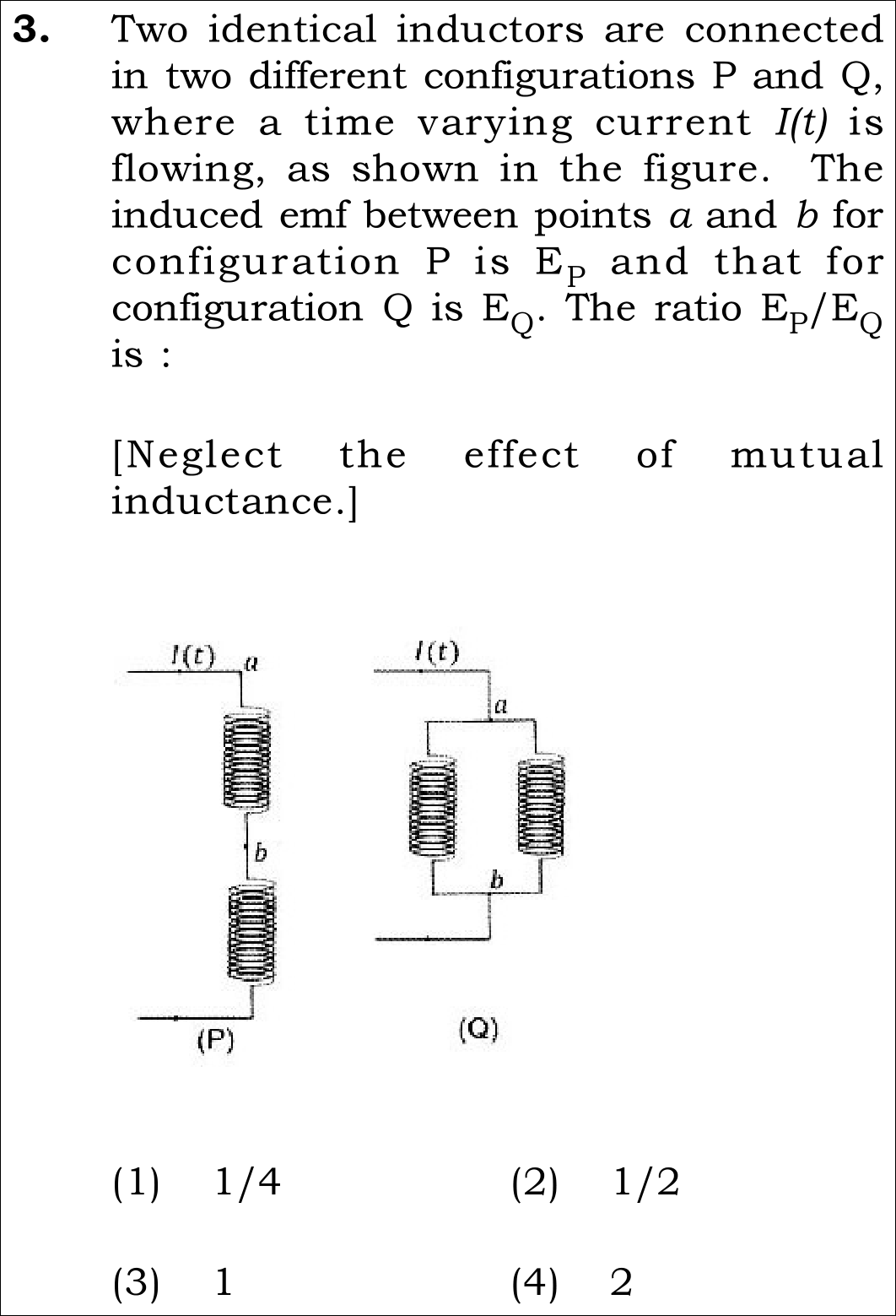
Look closely at terminal placement: a-b in P is across a single inductor!
Step-by-Step Rigorous Workflow & Mathematical Proof
Analyze Configuration P (Series Branch with Localized Voltage Tap)
Carefully observe the diagram for P: two identical inductors are in series, but terminals a and b are located at the top and bottom of the FIRST inductor only.
- • Because the inductors are in series, the same current I(t) flows through both.
- • The induced EMF E_P measured strictly across a and b is the EMF of that single inductor: E_P = L * (dI/dt).
Analyze Configuration Q (Parallel Inductor Bank)
In configuration Q, the two identical inductors are connected in parallel between terminal nodes a and b.
- • Total current I(t) divides equally between two identical branches: I_1 = I_2 = I(t) / 2.
- • Induced EMF across terminals a and b: E_Q = L * (d(I/2)/dt) = (L/2) * (dI/dt).
Calculate the Ratio E_P / E_Q
Divide the magnitude of E_P by E_Q:
- • The factor L * (dI/dt) cancels cleanly from numerator and denominator.
- • Leaves the exact dimensionless ratio: 2.
360° Option Elimination Engine Key Feature
Diagnose every choice: Know exactly why the right option works and why distractors fail.
Double-inverted ratio.
Reciprocal error.
Ignores current division in parallel branches.
100% scientifically verified and matches Official NTA Final Answer Key.
NTA Trap Alert: The Full Series Voltage Assumption Trap
Many students do not look at the letter "b" in figure P and assume E_P is measured across BOTH inductors in series (which would give 2L, leading to ratio 2L / (L/2) = 4).
Core NEET Syllabus Standard
"Induced EMF across an inductor is e = -L (di/dt). For N identical parallel inductors, equivalent inductance is L/N."