MyCompetitiveExams Logo MyCompetitiveExams
Search 1,140+ Questions
Chapters, formulas, speed tricks
→
⚡ Brahmastra NEET 2027
720 MARKS

Dynamic 180-question full-length simulator mixed dynamically from all 6 years for 2027 & 2026 aspirants.

Launch Brahmastra 2027 Test →
Start Practice →
100% Free · No Login Required
Q.39 Physics ⭐ 360° Option Elimination Active
Vault ↗

NEET 2021 Physics Question 39 Solution

Topic: Semiconductor Electronics: Materials, Devices and Simple Circuits · Official NTA Booklet Code M1
NEET 2021 Physics Question 39: Combinational Logic Gates: Timing Waveform and Boolean Analysis

Question

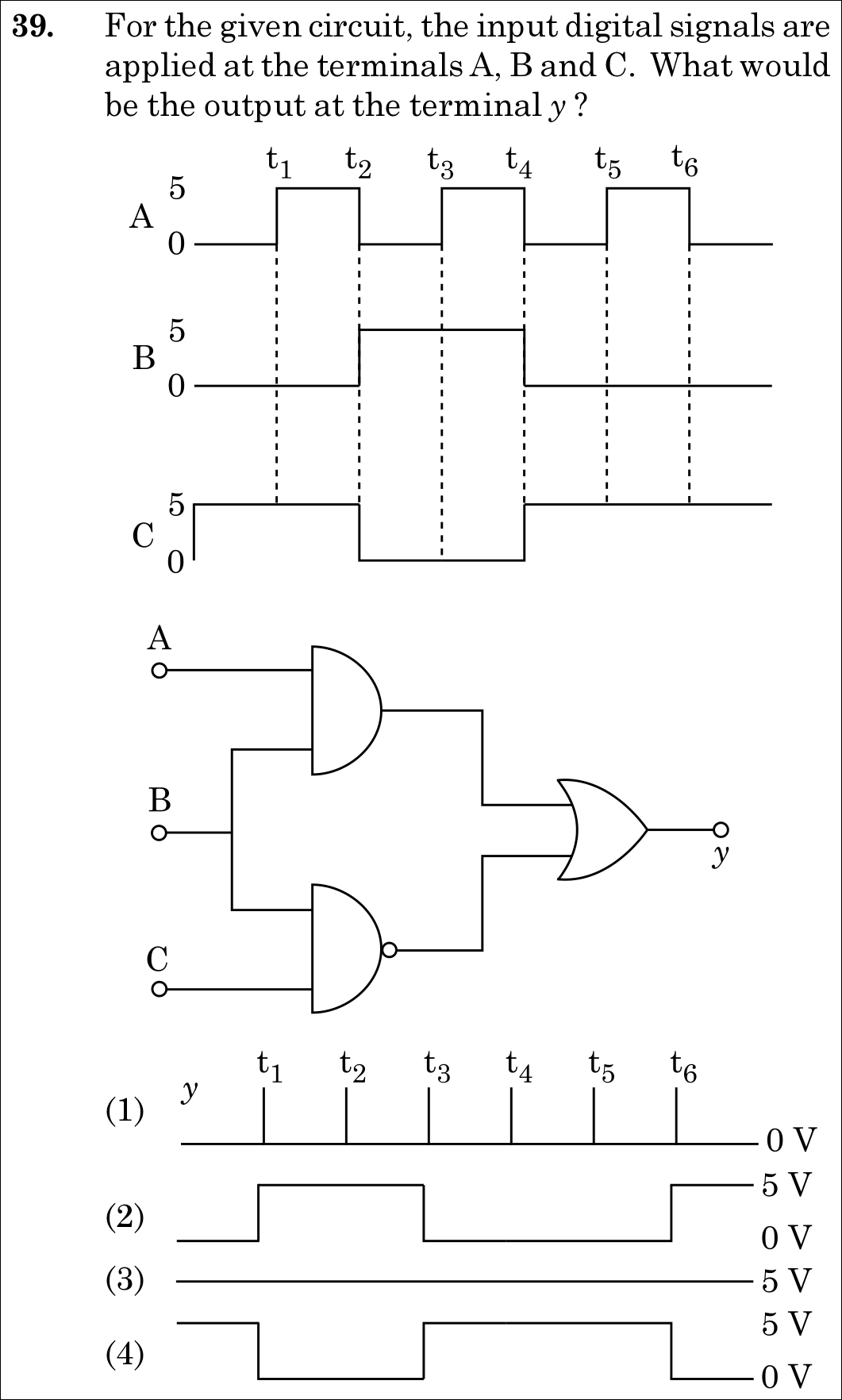
For the given circuit, the input digital signals are applied at the terminals A, B and C. What would be the output at the terminal y?

✓
Verified Against NTA Final Answer Key
Option (3) : Graph (3): Constant high output at 5 V across all time intervals
📚 Semiconductor Electronics: Materials, Devices and Simple Circuits Medium
📋 Given Parameters & Problem Setup
Gate 1 (Top) AND gate with inputs A and B (Output = A · B)
Gate 2 (Bottom) NAND gate with inputs B and C (Output = (B · C)')
Gate 3 (Output) OR gate receiving outputs of Gate 1 and Gate 2 (y = (A · B) + (B · C)')
⚡

The 30-Second Exam Hall Shortcut: ⚡ NAND Gate is ALWAYS 1 because B and C are NEVER simultaneously 1!

⏱️ Save ~30 seconds

Inspect the waveform: When B=1B = 1 (5 V5\text{ V}, between t2t_2 and t4t_4), CC is strictly 00! When C=1C = 1, BB is strictly 00! Thus, BB and CC are NEVER simultaneously 1   ⟹  B⋅C=0\implies B \cdot C = 0 at all times! Therefore, the NAND gate output B⋅C‾=1\overline{B \cdot C} = 1 (5 V5\text{ V}) permanently! Since an OR gate with a constant 1 input outputs 1, y=5 Vy = 5\text{ V} constantly! Match Graph (3)!

1 Boolean expression: y=(A⋅B)+B⋅C‾y = (A \cdot B) + \overline{B \cdot C}.
2 Examine inputs B and C in the timing diagram: - Before t2t_2: B=0,C=1  ⟹  B⋅C=0B = 0, C = 1 \implies B \cdot C = 0. - t2t_2 to t4t_4: B=1,C=0  ⟹  B⋅C=0B = 1, C = 0 \implies B \cdot C = 0. - After t4t_4: B=0,C=1  ⟹  B⋅C=0B = 0, C = 1 \implies B \cdot C = 0.
3 At every instant of time, B⋅C=0B \cdot C = 0.
4 Therefore, the output of the NAND gate is B⋅C‾=0‾=1\overline{B \cdot C} = \overline{0} = 1 (5 V5\text{ V}) continuously.
5 The OR gate output is y=(A⋅B)+1=1y = (A \cdot B) + 1 = 1 (5 V5\text{ V}) continuously across all intervals.
6 Match Graph (3).
🛡️
Why You Can 100% Trust This Shortcut: Canonical Boolean algebra identities (X+1=1X + 1 = 1) and digital waveform timing analysis.
📐

Step-by-Step Rigorous Workflow & Mathematical Proof

Step 1

Formulating the Output Boolean Function

Analyze the logic gate circuit: - Gate 1 is an AND gate with inputs AA and BB, giving output Y1=A⋅BY_1 = A \cdot B. - Gate 2 is a NAND gate with inputs BB and CC, giving output Y2=B⋅C‾Y_2 = \overline{B \cdot C}. - Gate 3 is an OR gate combining Y1Y_1 and Y2Y_2:

y=Y1+Y2=(A⋅B)+B⋅C‾y = Y_1 + Y_2 = (A \cdot B) + \overline{B \cdot C}
Step 2

Timing Analysis for Each Time Interval

Construct the interval-by-interval digital truth table from the provided waveforms (5 V≡15\text{ V} \equiv 1, 0 V≡00\text{ V} \equiv 0): - 0<t<t10 < t < t_1: A=0,B=0,C=1  ⟹  Y1=0,Y2=0‾=1  ⟹  y=0+1=1A = 0, B = 0, C = 1 \implies Y_1 = 0, Y_2 = \overline{0} = 1 \implies y = 0 + 1 = 1 (5 V5\text{ V}) - t1<t<t2t_1 < t < t_2: A=1,B=0,C=1  ⟹  Y1=0,Y2=0‾=1  ⟹  y=0+1=1A = 1, B = 0, C = 1 \implies Y_1 = 0, Y_2 = \overline{0} = 1 \implies y = 0 + 1 = 1 (5 V5\text{ V}) - t2<t<t3t_2 < t < t_3: A=0,B=1,C=0  ⟹  Y1=0,Y2=0‾=1  ⟹  y=0+1=1A = 0, B = 1, C = 0 \implies Y_1 = 0, Y_2 = \overline{0} = 1 \implies y = 0 + 1 = 1 (5 V5\text{ V}) - t3<t<t4t_3 < t < t_4: A=1,B=1,C=0  ⟹  Y1=1,Y2=0‾=1  ⟹  y=1+1=1A = 1, B = 1, C = 0 \implies Y_1 = 1, Y_2 = \overline{0} = 1 \implies y = 1 + 1 = 1 (5 V5\text{ V}) - t4<t<t5t_4 < t < t_5: A=0,B=0,C=1  ⟹  Y1=0,Y2=0‾=1  ⟹  y=0+1=1A = 0, B = 0, C = 1 \implies Y_1 = 0, Y_2 = \overline{0} = 1 \implies y = 0 + 1 = 1 (5 V5\text{ V}) - t5<t<t6t_5 < t < t_6: A=1,B=0,C=1  ⟹  Y1=0,Y2=0‾=1  ⟹  y=0+1=1A = 1, B = 0, C = 1 \implies Y_1 = 0, Y_2 = \overline{0} = 1 \implies y = 0 + 1 = 1 (5 V5\text{ V}) - t>t6t > t_6: A=0,B=0,C=1  ⟹  Y1=0,Y2=0‾=1  ⟹  y=0+1=1A = 0, B = 0, C = 1 \implies Y_1 = 0, Y_2 = \overline{0} = 1 \implies y = 0 + 1 = 1 (5 V5\text{ V})

Step 3

Conclusion

The output yy is logic high (5 V5\text{ V}) uniformly throughout all time intervals, corresponding to the straight horizontal line at 5 V5\text{ V} in Graph (3).

⭐

360° Option Elimination Engine Key Feature

Diagnose every choice: Know exactly why the right option works and why distractors fail.

4-Option Deep Scan
1 1
✗ Incorrect
Verdict & Scientific Reason:

The output is logic high 1 (5 V), not logic low 0.

⚠️
Student Fallacy (Why candidates pick this trap): Assuming all gates cancel each other out to zero.
2 2
✗ Incorrect
Verdict & Scientific Reason:

Represents only the AND gate output (A⋅BA \cdot B), ignoring the NAND gate input to the OR gate.

⚠️
Student Fallacy (Why candidates pick this trap): Neglecting the bottom NAND gate branch.
3 3
✓ 100% Correct
Verdict & Scientific Reason:

Exact output: Y2=1Y_2 = 1 for all times, maintaining y=1y = 1 (5 V5\text{ V}) constantly.

💡
Why this is airtight: None; rigorous timing and Boolean algebra proof.
4 4
✗ Incorrect
Verdict & Scientific Reason:

Incorrect timing analysis.

⚠️
Student Fallacy (Why candidates pick this trap): Applying inversion at the wrong stage.
⚠️

NTA Trap Alert: OR Gate Domination Trap

Students spend considerable time sketching out complicated pulse widths for the AND gate, failing to notice that the NAND gate output is ALWAYS 1. In Boolean logic, any input of 1 to an OR gate permanently locks the output to 1 (X+1=1X + 1 = 1).

🛡️ How to avoid the -1 mark: Use Boolean simplification first: y=AB+BC‾y = A B + \overline{B C}. Since BB and CC are never 1 simultaneously, BC‾=1\overline{B C} = 1 always, making y=1y = 1 always.
📖

Core NEET Syllabus Standard

NCERT Physics · Semiconductor Electronics: Materials, Devices and Simple Circuits Standard Benchmark
Core Scientific Principle Tested:

"Boolean logic rules: A⋅0=0A \cdot 0 = 0, 0‾=1\overline{0} = 1, and X+1=1X + 1 = 1. When one input to an OR gate is perpetually 1, output is constantly 1."

Syllabus Focus: Logic Gates (AND, NAND, OR)
✓ Core NEET UG Syllabus Anchor Syllabus & Academic Standards ↗

Ready to attempt under real exam pressure?

Test your speed and accuracy in the authentic 200-minute timed NTA simulator.

Launch NEET 2021 CBT Test →

Spotted a mistake in this solution? Report an error (support@mycompetitiveexams.com)

⚖️ Legal & Fair Dealing Notice: Sourced from publicly released NEET 2021 question papers and NEET answer keys for private study, research, and non-commercial educational practice under Fair Dealing (Section 52(1)(a) of the Indian Copyright Act, 1957). Not affiliated with or endorsed by NTA or NMC.

Solve 4 NEET Questions a Day — One per Subject

Cover all 1,140 official NEET questions in 285 days at your own pace. Progress is saved on your device. No login needed.